Cisco Certified Network Associate
I took down some notes from udemy lecture videos.
1.2 Introduction: Network Basics
IP address
- Protocol (1): a set of rules that user has to follow to have a proper communication, just like a standard language (English, French, ...) to communicate. There are different kids of protocols:
- TCP/IP developed by Department of Defence
- NETBIOS developed by MS
- IPx/SPx by Novell
- Appletalk by Apple
- OSI by ISO
- and so on.
- Protocol (2): So everybody was using different protocols. But later on, TCP/IP protocol was selected to be standard language, because of the Internet which is the biggest community. So even if my device is from Microsoft, it has to support TCP/IP to connect to the Internet. Same if you are using an Apple machine.
- TCP/IP Protocol (1): it also has different protocols of its own:
- HTTP: web pages in general
- FTP: send files
- SMTP: emails
- POP3
- DNS
- DHCP
- IP addressing in TCP/IP:
- IP address is a unique string of numbers separated by periods that identifies each computer using the Internet Protocol to communicate over a network, just like every person is identified with some name.
- IP address is a logical address given to each device in the network and is used to identify the device within the network.
- IPv4 is a 32 bit address (still used). General found in decimal format, but expressed firstly in binary form in 32 bits. So an example could be: 01010101 00000101 10111111 00000001. These bits can be separated into 4 Octets (8 bits) as seen, and these can be converted into a decimal format: 85.5.191.1. These are (I guess... supposedly) these bits are unsigned binary bits. Minimum decimal value of an octet: 0. Maximum: 255. So, the smallest IP address (if you want) is 0.0.0.0 and the biggest 255.255.255.255. IPv4 addresses can be divided into 5 classes (as seen in the pic)
- IPv6 is a 128 bit address. Found in hexadecimal format, it has 16 bits blocks of eight (so total = 16 * 8 = 128 bits). So for example: fe80::aede:48ff:fe00:1011:341e:43d1:0a1a
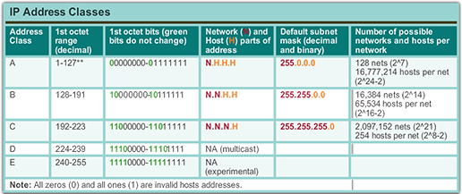
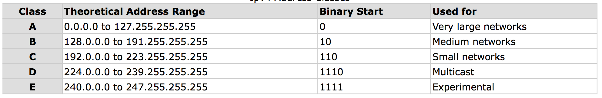
- Classes in IPv4: So if you are too look at an IP address and decide which class it belongs to, just look at the first octet and decide which range it belongs to. Ex. 150.*.*.* belongs to B class.
- A-C are used in LAN&WAN.
1.3 Introduction: Network devices
- Switch
- WAP
- Routers
- Firewall
- IP Phones / Voice devices
- Home routers
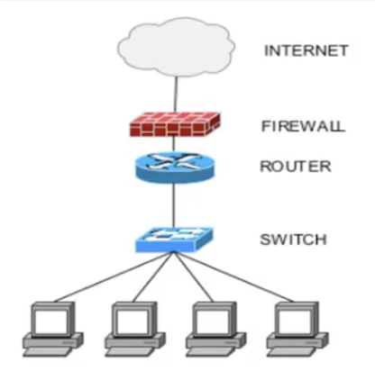
Cisco switch (hubs)
provides interconnection between different PCs through LAN (Local Area Network). If you want to connect more than four or five PCs, switch may be a good choice.
Wireless Access Point
Connect devices without a wire. This network device has antennae (which is called AP, Access Points) that radiates signals to nearby locations.
Cisco routers
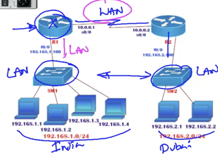
router provides WAN connection when you want to connect multiple LANs. For example, you have different branches of a company physically distant from each other. And you wanna connect the switches in these branches with each other, so that you have all the computers connected. What you want to do is to have a router for each branch that would be connected to the switch (LAN) and also the other router in the other branch through WAN.
provides interconnection between different PCs through LAN (Local Area Network). If you want to connect more than four or five PCs, switch may be a good choice.
Wireless Access Point
Connect devices without a wire. This network device has antennae (which is called AP, Access Points) that radiates signals to nearby locations.
Cisco routers
router provides WAN connection when you want to connect multiple LANs. For example, you have different branches of a company physically distant from each other. And you wanna connect the switches in these branches with each other, so that you have all the computers connected. What you want to do is to have a router for each branch that would be connected to the switch (LAN) and also the other router in the other branch through WAN.
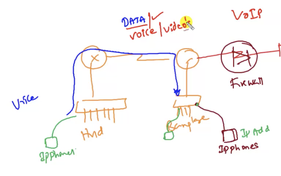
Cisco firewall
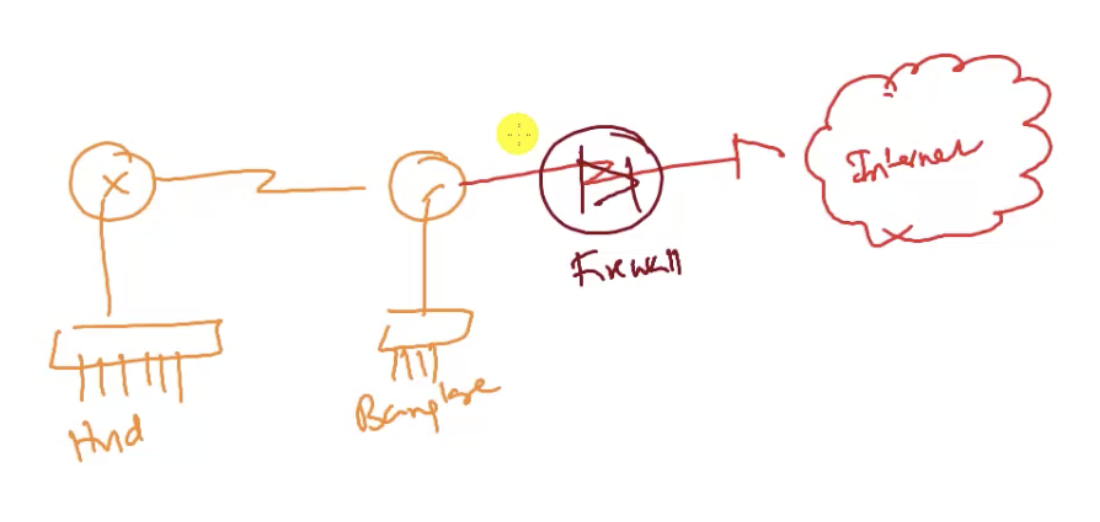
firewall protect the network from external traps. For example, you have two different branches of office just like above picture. But also imagine (and in reality it happens as well) that the router R2 is also connected to the Internet where a potential attacker exists. This attacker may come into the network through the Internet and then the router R2. So you want to set up a firewall between the Internet and the router to filter every packets to protect the network from some unauthorised packets from coming in. And it will also ensure that the traffic coming into the network will not go out with some information taken.
firewall protect the network from external traps. For example, you have two different branches of office just like above picture. But also imagine (and in reality it happens as well) that the router R2 is also connected to the Internet where a potential attacker exists. This attacker may come into the network through the Internet and then the router R2. So you want to set up a firewall between the Internet and the router to filter every packets to protect the network from some unauthorised packets from coming in. And it will also ensure that the traffic coming into the network will not go out with some information taken.
|
|
IP phones / Voice devices
IP phones are connected to the LAN(=switch) (just like a computer) and you can configure your voice traffic to go all the way from one branch to another branch without having to use telephone lines but through VOIP protocol (you could even send voice, videos ...).
IP phones are connected to the LAN(=switch) (just like a computer) and you can configure your voice traffic to go all the way from one branch to another branch without having to use telephone lines but through VOIP protocol (you could even send voice, videos ...).
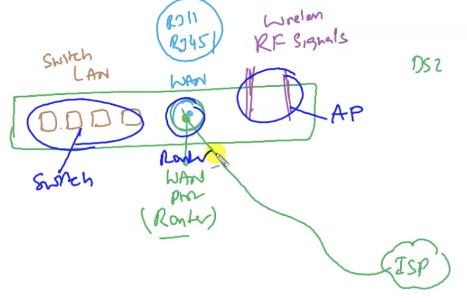
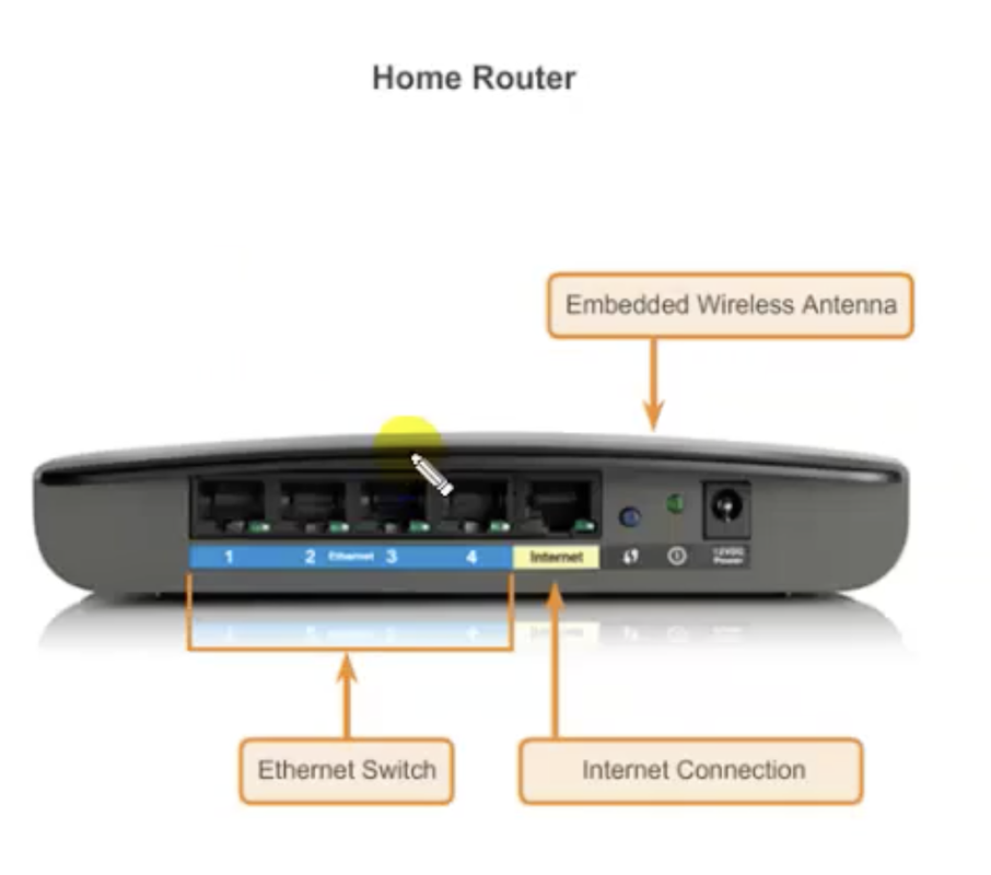
Home routers
They have LAN ports doing the job of switches (but only few ports). They also have WAN ports to connect to the ISP(Internet service provider) to do the job of a router.
Normally, if you have a broadband service, you can use it for only one computer, but if you want to share it among multiple computers, you can do so by plugging the broadband connection into the router (home router) that allows multiple devices to use the broadband connections.
Home routers also have wireless APs.
In summary, switch(LAN), WAN(Wide Area Network)(=role of router to connect to the Internet), and WLAN in just one single network device = home router.
|
|
1.4 Introduction: CCNA
Cisco is the leading manufacturer of networking devices (covered in the previous chapter)
R/S (routing and switching): specialized track for LANs (switches) and routers.
R/S (routing and switching): specialized track for LANs (switches) and routers.
2.1: TCP-IP addressing: basics
TCP/IP(Transmission Control Protocol/Internet Protocol)
A protocol is a set of rules to follow to have a proper communication. Among different protocols, TCP/IP was selected to be the standard protocol just because the Internet supports TCP/IP protocol. But this was not happening in the past. TCP/IP can be used between more than two of any network devices.
TCP/IP addressing
Every device in the network has to be given a unique logical identifier, which is an IP address. It is a network layer address (layer 3, which is based on OSI model)
IPv4 vs IPv6
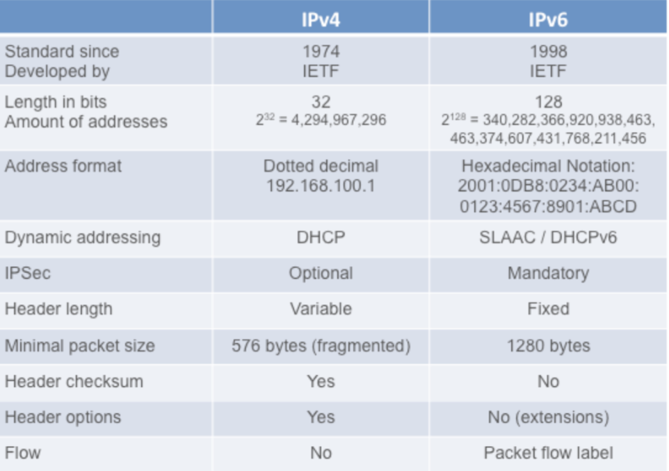
To keep up with the number of people using the Internet, IPv6 was released. But they also came up with NAT(Network Address Translation), which is the reason we can still use IPv4. Before NAT, 1000 thousand users means 1000 IP addresses. But NAT allows more than 60,000 users to use only one IP address.
2.2 TCP/IP addressing: IPv4 Classification
see 1.2 for the first part.
Assigning an IPv4 address to a host
Different options:
Assigning an IPv4 address to a host
Different options:
- Automatically get an IP address: What you do is not assigning each computer in the network (think of a company with a lot of coms) one by one, but connecting them to DHCP (Dynamic Host Configuration Protocol (DHCP) is a client/server protocol that automatically provides an Internet Protocol (IP) host with its IP address and other related configuration information such as the subnet mask and default gateway) server running an operating system with a certain configuration that defines the range of IP address (what number it starts with and ends with, something like that) to automatically assign an IP address to each computer.
- Manually set an IP address: (majorly used for this CCNA tutorial)
Check IP address
Types of communication in IPv4
There are three different ways for hosts to communicate:
There are three different ways for hosts to communicate:
- Unicast:one-to-one communication. For example, you have a LAN with many devices connected. And even though you have many devices connected, it may be that one device connected to LAN will make unicast connection when sending information to another device over LAN. Only two devices participate.
- Broadcast:one-to-all. One device sends information to all other devices listening to it. There are two ways that switches can broadcast, which is going to be covered later.
- Multicast:one-to-many packet transmission. Only a group of selected devices are involved in the communication. For example in LiveTV, Radio broadcasting, distance learning, videoconferencing, ... So as we know, different IP addresses ranging from 224.0.0.0 to 239.255.255.255 will identify different multicast groups (class D). This is not reserved for normal PCs. Even if you try to assign some IP in this group to a personal computer, it will not be a valid input.
2.3 TCP/IP addressing: Network & Host portions
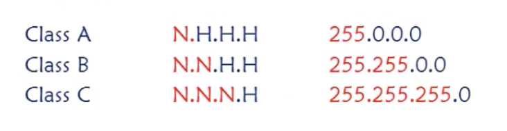
Different arrangements of network and host portions for class A, B, and C
Class A: N.H.H.H
Class B: N.N.H.H
Class C: N.N.N.H
Host: a specific (single) device in the network
Network: a set of devices (= network. like a router?)
It's just like a floor and room number. 203 means a room in the 2nd floor. 301 means a room in the 3rd floor. The first number identifies a floor, and the following numbers identify a room. Similar thing for IPs.
For example, you have two distinct computers with IP addresses: 192.168.1.1 and 192.168.2.1 and you wanna make sure they are connected to the same network and communicate with each other. So the first thing you wanna do with these IP addresses is to (1) identify a class. So 192 belongs to class C (192-223).
Class C has three network portions, and discover that the third network portions between these IP addresses are different. Therefore, they are not on the same network. Remember that the whole thing is determined based on the class the IP address belongs to. So these devices with these addresses will never logically talk to each other.
Example: designing a network
- you have 200 devices connected through LAN (they are in the same network (= same network portion) and they are working fine).
- you need to assign IP addresses to these devices.
- you have a C-class IP address.
- if you have the network portion as 192.168.10, you must not change this.
- And you can change the last portion which is the host portion, and with this portion you can have 256 different unique addresses (from 0 to 255). So it's fine , it satisfies the number of devices (200)
- But what if you get to have bigger number of devices in your company and you need to reconfigure IP address assignment?
- You may want to change to B-class that offers bigger number of hosts to be in the same network. So the first two portions will stay the same always, for example: 172.16. and you are free to change the last to portions for hosts. In total, you have 256*256 = 65536 devices that can be identified with unique IP addresses.
- In case you switch to class A, you can have 256^3 different IP addresses in the same network.
2.4 TCP/IP addressing: Broadcast ID - subnetmask
Reserved IP addresses
- Network address: first IP of the range. identifies the entire network (when you need to show it to external networks, for example). It has all zero's in the host portion.
- Broadcast address: last IP of the range. used to send the broadcast (to all the devices in the network) over the same network. All one's in the host portion (binary).
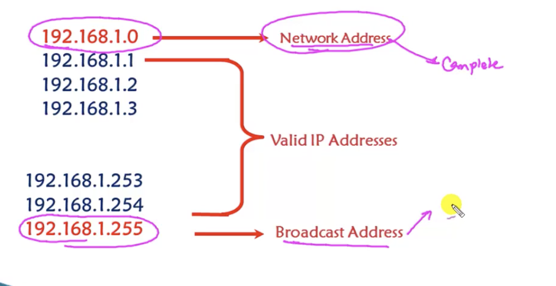
class C example. Host portion is only the last part.
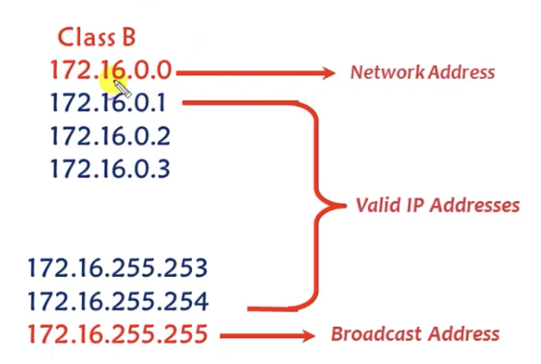
class B example. Host portion is the last two octets.
- so you cannot assign a broadcast ID (IP address) or the network ID (IP address) to any device in the network.
Example: network ID and broadcast ID of the network to which some given address belongs to
150.12.10.10 would belong to class B. So it has two host portions. Then the network ID will be 150.12.0.0 and the broadcast ID will be 150.12.255.255. Any other addresses within the range can be used.
150.12.10.10 would belong to class B. So it has two host portions. Then the network ID will be 150.12.0.0 and the broadcast ID will be 150.12.255.255. Any other addresses within the range can be used.
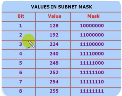
Subnet-mask
- Differentiates the network portion and the host portion.
- binary 1 represents network portion
- binary 0 represents host portion
- for example, for class A, the subnet-mask is 255.0.0.0.
Additionally reserved addresses (+ recap)
- class D&E
- Network ID & Broadcast ID
- 0.x.x.x: invalid address
- 127.x.x.x: for loopback address
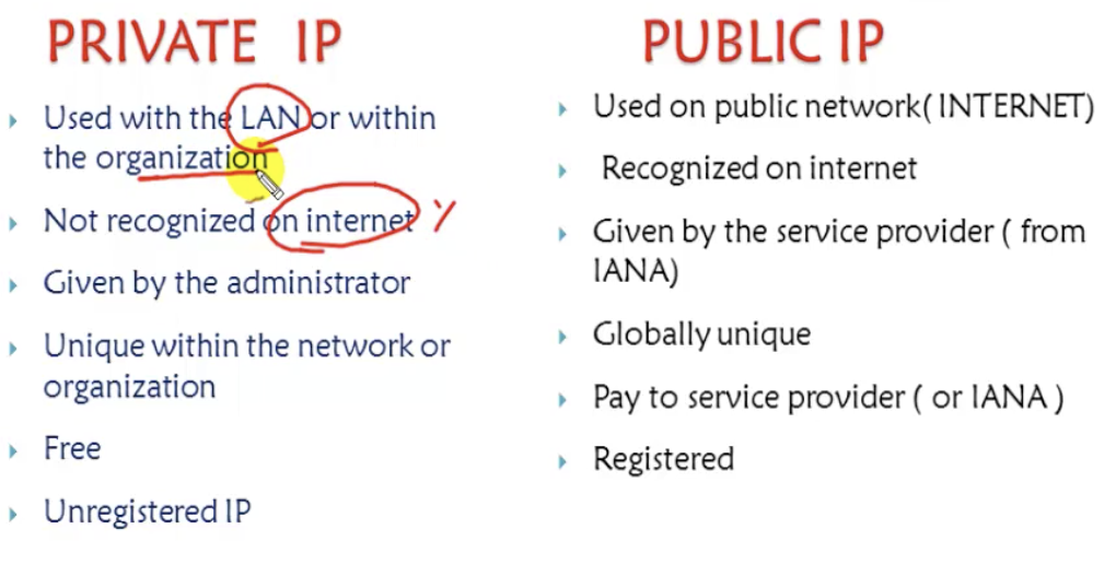
2.5 TCP/IP addressing: private & public IP
Private vs public IP: Why?
- Consider a situation where you have a computer in your company. You have an IP address of 192.168.1.1 and are trying to access a server on the Internet. But the problem is that, there are some multiple users in different regions who are using the same IP address. But the server has to reply back to the correct IP address that has sent the request, but it does not know it.
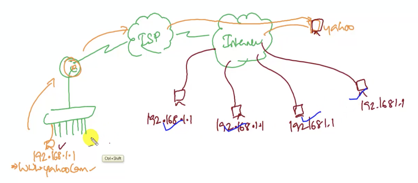
- So that's the reason why we use the public IP. This IP is globally unique (especially for registered public IP). But what about the users who still want to communicate without the Internet?
- Use private addresses. It is not recognized by the Internet.
- When you want to both connect internally (in the private network) and also externally (with the Internet), you can do so: the router can get translate the private IP address to the public IP. After sending requests to a server on the Internet, the router will receive the reponse on the behalf of the public IP address. And it can again translate the IP address into a private one, thereby successfully transferring the requested information to the specific private IP. This process is called NAT(Network access translation).
Private vs Public IP address: details
Only some 'range' is chosen in each class to be reserved for private IP addresses:
Only some 'range' is chosen in each class to be reserved for private IP addresses:
- Class A: 10.0.0,0 to 10.255.255.255 (only one network)
- Class B: 172.16.0.0 to 172.31.255.255 (only 16 networks)
- Class C: 192.168.0.0 to 192.168.255.255 (only 256 networks)
Private vs Public IP address: example
- 172.35.*.* would be a public address
Assignment of IP addresses
IANA (Internet assigned numbers authority) supervises assignment of public IP addresses. Administration is also divided into 5 big regions: Africa, North America, South America, Europe, and Asia&Oceania
IANA (Internet assigned numbers authority) supervises assignment of public IP addresses. Administration is also divided into 5 big regions: Africa, North America, South America, Europe, and Asia&Oceania
3.1 Subnetting-FLSM: why do we need subnetting
Subnetting
a process of dividing a single network into multiple smaller network. Subnetting helps minimize wastage of IP addresses.
Why divide the network at all?
a process of dividing a single network into multiple smaller network. Subnetting helps minimize wastage of IP addresses.
Why divide the network at all?
- Consider a company that's got different departments.
- Each department should not communicate with each other.
- But they should be in the same LAN.
- Then, you could configure them in logically different networks. For example:
- 192.168.1.0 for dept A, 192.168.2.0 for dept B, 192.168.3.0 for dept C, 192.168.4.0 for dept D. This is possible because class C has three network portions, so each address that belongs to each of these networks should not be able to communicate with each other.
- But the problem is, there's a lot of wastage of IP addresses. For example, if you only have 50 devices each department, you are not going to use 206 IP addresses anyways (because it's class C)
- Similarly, if you want to buy 10 IP addresses, you face a problem where you should by 256 of class C IP addresses.
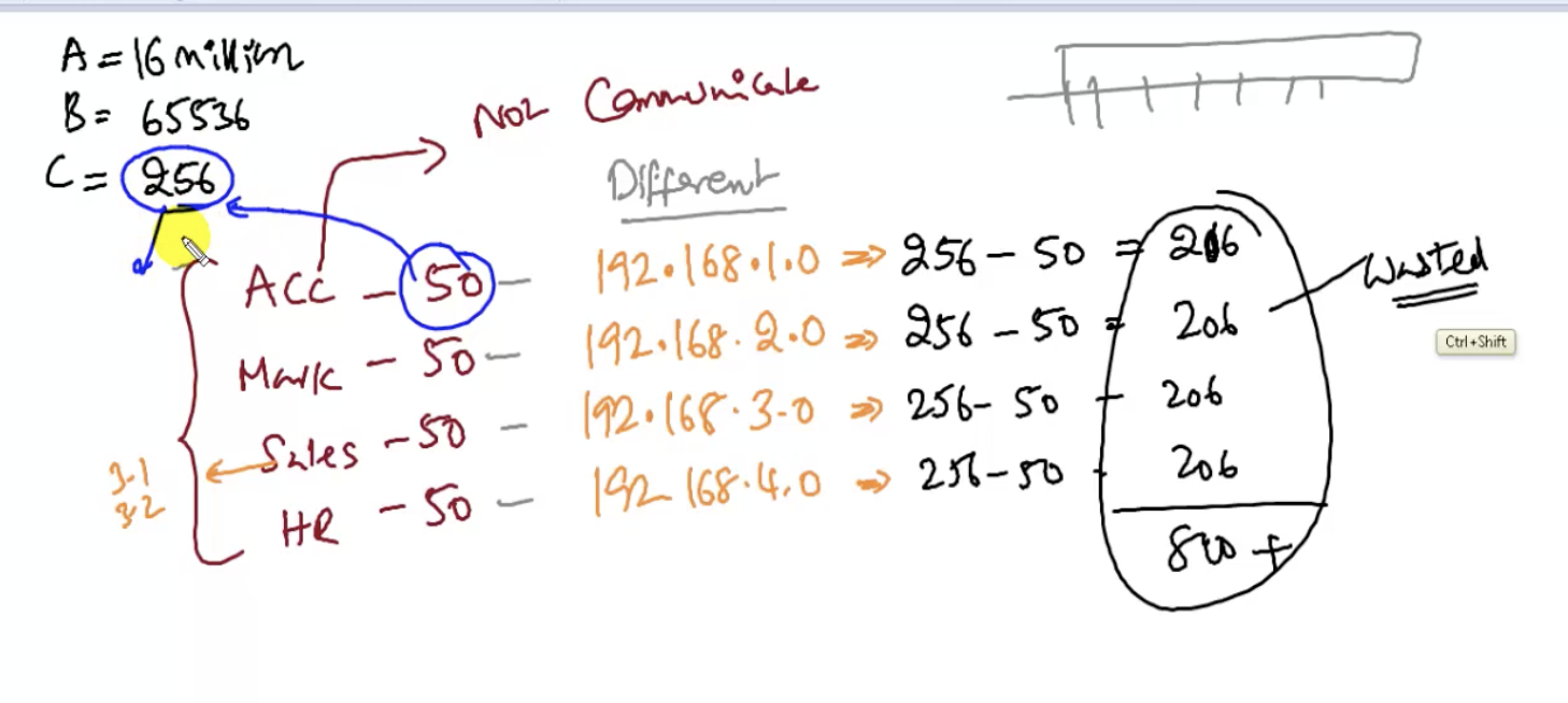
illustration of above example.
The solution is to divide one network into smaller networks. This process of dividing a network into multiple networks is called subnetting. The main reason for subnetting is that the default number of possible IP addresses are too big.
Subnetting: details
Two types of subnetting:
Two types of subnetting:
- FLSM: fixed length subnet mask. each divided network will be an equal size.
- VLSM: variable length subnet mask . it does not have. to be equal.
- based on requirements. See how many devices have to be connected (based on number of hosts) or see how many networks have to be built (based on number of networks needed)
- based on # hosts: 2^(host bits) - 2 >= requirement
- based on # networks needed: 2^(network bits) >= requirement
- Converting host bits into network bits (reducing number of host bits) (= converting 0's into 1's)
- So in class A, you have N.H.H.H (host bits = 24)
- class B, N.N.H.H (host bits = 16)
- class C, N.N.N.H (host bits = 8)
- for example, in class C, the number of host bits could change to 6 or 5 (reduced in number), so that we have bits to differentiate networks.
- So in subnetting, the number of host bits is reduced. So the network size changes as well. For example, if you have cut down the host bits to 4, the network size (# available IP addresses) is only 2^4 = 16.
3.2 Subnetting-FLSM: FLSM C-class with 50 hosts (example)
Take an example of C-class network.
- You want to have 50 hosts in each divided network.
- Use the formula: 2^h - 2 >= requirement
- The requirement is 50, so: 2^h - 2 >= requirement
- Therefore, get h = # host bits as 6 (you could only choose the number of host bits from the power of 2. you cannot get the exact h to exactly match the requirement. So take h=6 anyways.)
- Then you have: 2^6 - 2 >= 50. You minus 2 because of network and broadcast IDs. So the result is 64-2 = 62 >= 50.
- The required host bits for C-class IP address is 6. This means you are going to get a subnet-mask of:
- 11111111 11111111 11111111 11000000 (255 255 255 192), NOT:
- 11111111 11111111 11111111 0000000 (255 255 255 0).
- So host bits = 6 means network bits = 26.
- In sum, to get more networks, reduce host bits.
- The range of this network is: 2^# host bits.= 2^6 = 64. This network can now be divided into 4 different networks:
- 0 to 63
- 64 to 127
- 128 to 191
- 192 to 255
- Of course, the network ID and the broadcast ID will be the first and the last IP address within the range of the divided network. (for the first network above, 192.168.1.0 and 192.168.1.63 in a C class network may be them respectively)
3.3 Subnetting-FLSM: FLSM C-class with 30 hosts (example)
Take an example of C-class network.
- The requirement is 30 hosts.
- Do the formula again: 2^h - 2 >= 30
- h = 5. You exactly get 30 then for the valid host addresses in one divided network.
- So the subnet mask will be:
- 11111111 11111111 11111111 11100000 (=255.255.255.224)
- This means 27 network bits.
- Actually there are only 8 possible subnet masks as we could expect.
- And the range will be: 2^h = 2^5 = 32 addresses.
- formula: # of subnets you are going to get: 2^converted network bits = 2^3 = 8 subnets.
- 0-31
- 32-63
- 64-95
- 96-127
- 128-159
- 160-191
- 192-223
- 224-255
3.4 Subnetting-FLSM: Understanding subnets
Suppose we've got two computers: 192.168.1.10 and 192.168.1.100. Both are using the default subnet mask: 255.255.255.0. And our question is: do they belong to the same network or different networks?
Yes. They belong to the same network.
h=8. The host bit does not change.
The size of the network = 2^h = 2^8 = 256.
Thus, the range = [0, 255]
Another example. Same computers and their IP's, but the subnet mask is now 255.255.255.192. Do they belong to the same network? No. They are in different networks.
h = 6. The host bit has changed.
The size of the network = 2^h = 2^6 = 64.
So, one subnet only has 64 IP Addresses in total.
This means 192.168.1.10 is in the subnet that has the range of [192.168.1.0, 192.168.1.63] and 192.168.1.100 is in the subnet that has the range of [192.168.1.64, 192.168.1.127].
Therefore, they are in different networks.
Thus everything is based on the subnet mask. If the subnet mask changes, the network size and the network address and broadcast address also changes.
3.5 Subnetting-FLSM: FLSM B-class
The default network size for class B is 2^h, where h = 16.
This means the number of possible addresses by default in class B is 65536.
Let us divide the network into subnets of 1000 IP addresses.
1. Find out the number of host bits needed and the number of valid hosts:
2^h - 2 >= Requirement
2^h - 2 >= 1000
Therefore, h must be 10 because:
2^10 - 2 = 1024 - 2 = 1022 ( = the number of valid hosts)
2. Find out the subnet mask
Because h = 10, the subnet mask is:
11111111 11111111 11111100 00000000 (= 255.255.252.0),
NOT: 11111111 11111111 00000000 00000000
3. Find out the number of subnets
2^converted network bits = 2^6 = 64 subnets
4. Get the range of each subnet
Size of each subnet is 1024.
So, for example, if you decided to subnet 172.16.0.0 into subnets of size of 1024 addresses, the range of first subnet would be:
[172.16.0.0, 172.16.3.255],
because:
from 172.16.0.0 to 172.16.0.255 there are 256 addresses
from 172.16.1.0 to 172.16.1.255 there are 256 addresses
from 172.16.2.0 to 172.16.2.255 there are 256 addresses
from 172.16.3.0 to 172.16.3.255 there are 256 addresses
which make up to 1024 addresses.
5. Find out how many 'blocks' (from *.*.*.0 to *.*.*.255) are needed for a subnet of certain size:
# blocks = 2^h / 256 = 2^# host bits / 256 = 2^10 / 256 = 1024 / 256 = 4
3.6 Subnetting-FLSM: FLSM A-class
Say the requirement is 16,000 hosts for an A class and the address we are going to subnet is obviously 10.0.0.0.
1. Find # host bits needed
2^h - 2 >= requirement
2^h - 2 >= 16000
2^14 - 2 = 16384 - 2 >= 16000
2. Figure out the subnet mask
By default, A class has N.H.H.H (8/24), but it only needs 18/14 according to the requirement.
11111111 11111111 11000000 00000000 (= 255.255.192.0)
Thus, total network bits = 18
Converted network bits = 24 - 14 = 10
# subnets = 2^converted network bits = 2^10 = 1024 subnets
3. Get the range
Size of a subnet = 2^# host bits = 2^14 = 16384
# Blocks of addresses (from .0 to .255) needed = 2^# host bits / 256 = 64
So it would go like:
1st subnet has [10.0.0.0, 10.0.63.255]
2nd subnet has [10.0.64.0, 10.0.127.255]
3rd subnet has [10.0.128.0, 10.0.191.255]
4th subnet has [10.0.192.0, 10.0.255.255]
5th subnet has [10.1.0.0, 10.1.63.255]
and so on, until:
nth subnet has [10.255.192.0, 10.255.255.255]
When getting the range, remember:
if network size <= 128, you only increment the last portion: X.X.X.[this portion]
if network size >= 256, you increment from the third portion: X.X.[this portion].X and the number for the last X will stay the same always as 0 and 255 for a range.
if network size >= 65536, you increment from the second portion: X.[this portion].X.X
Don't be misled to think that C-class network only needs to increment on the last portion if it were to be subnetted. It could be other cases as well.
4.1 Subnetting-VLSM: Slash value
Slash value represents total network bits. It's another way of writing the subnet mask information.
Normally a diagram would have each device's IP address.
Say, we've got the IP address of one device, but we don't have the subnet mask yet:
129.168.1.100
Then it's C-class, so the default subnet mask is 255.255.255.0
But the network may be subnetted (in which case the subnet mask would be mentioned), yet if not mentioned, just assume that the subnet mask is default.
If the device's IP address is 192.168.1.100, and
the subnet mask is 255.255.255.224 (= 111111111 11111111 11111111 11100000),
instead of writing each of them like that, we could write:
192.168.1.100/27, and 27 is the total # of network bits (and the remaining 32-27 bits are used for host bits).
So without explicitly mentioning the subnet mask, if:
192.168.1.100/27 is mentioned, we should know that the # of network bits is 27, and therefore the subnet mask is:
111111111 111111111 11111111 111000000 = 255.255.255.224
Exercises
/12: 8 4 0 0 bits. Then the subnet mask is 255.240.0.0
/15: 8 7 0 0 bits. 255.254.0.0
/17: 8 8 1 0 bits. 255.128.0.0
/18: 8 8 2 0 bits. 255.192.0.0
/20: 8 8 4 0 bits. 255.255.240.0
/21: 8 8 5 0 bits. 255.255.248.0
/22: 8 8 6 0 bits. 255.255.252.0
/25: 8 8 8 1 bits. 255.255.255.254
/27: 8 8 8 3 bits. 255.255.255.224
/28:8 8 8 4 bits. 255.255.255.240
/30: 8 8 8 6 bits. 255.255.255.252
4.2 Subnetting-VLSM: VLSM C-class
say you've got branch offices and we have:
branch 1 with 100 hosts
branch 2 with 20 hosts
branch 3 with 10 hosts
branch 4 with 40 hosts
we 'could' go with default network but it would be a lot of waste.
we could also go with FLSM but it would be a lot of waste (the network size would be 128 because we need 100 hosts at one office)
but with VLSM, we could make the network size:
128 for 100 hosts
64 for 40 hosts
32 for 20 hosts
16 for 10 hosts
We still have some wastage in the IP addresses, but the amount of wastage is greatly reduced.
So let us start from the highest requirement (100):
1. Get the # of host bits needed.
2^h - 2 >= requirement
2^h - 2 >= 100
2^7 - 2 = 128 - 2 >= 100
# of host bits = 7
2. Get the subnet mask
# of host bits needed is only 7, not 8, so:
11111111 11111111 11111111 10000000
= 255.255.255.128
3. Get the range (this is where it gets different from FLSM)
The network size is 2^h, so 2^h = 2^7 = 128
So it would be:
[192.168.1.0/25, 192.168.1.127/25]
The next requirement is 40. So:
1. Get h
requirement = 40
2^6 - 2 = 64 -2 >= 40
h = 6
# of valid host addresses = 62
2. Get the subnet mask
11111111 11111111 111111111 11000000
= 255.255.255.192
3. Get the range (this is where it gets really different)
The first requirement has already taken up [192.168.1.0/25, 192.168.1.127/25].
So this requirement can take the subnet of [192.168.1.128/26, 192.168.1.191/26].
Notice that the subnet mask, and therefore the network sizes of subnets are different.
The next requirement is 20. So:
1. Get h
requirement = 20
2^5 - 2 = 32 - 2 >= 20
h = 5
2. Get the subnet mask
11111111 11111111 11111111 11100000
= 255.255.255.224
3. Get the range
The first requirement has taken [192.168.1.0/25, 192.168.1.127/25].
The second requirement has taken the subnet of [192.168.1.128/26, 192.168.1.191/26].
This requirement can take [192.168.1.192/27, 192.168.1.223/27] (it's not 192+32 = 224. It's 192+32-1= 223 because 192 is also included in the range)
The next requirement is 10.
1. Get h
requirement = 10
2^4 - 2 = 16 - 2 >= 10
h = 4
2. Get the subnet mask
11111111 11111111 11111111 11110000
= 255.255.255.240
3. Get the range
The first requirement has taken [192.168.1.0/25, 192.168.1.127/25].
The second requirement has taken [192.168.1.128/26, 192.168.1.191/26].
The third requirement has taken [192.168.1.192/27, 192.168.1.223/27].
This requirement can take [192.168.1.224/28, 192.168.1.239/28].
What about the remaining addresses in the network?
you can just use them. In this case, the remaining addresses are [192.168.1.240/28, 192.168.1.255/28]. You can subnet them, or you can just use them as they are now (/28)
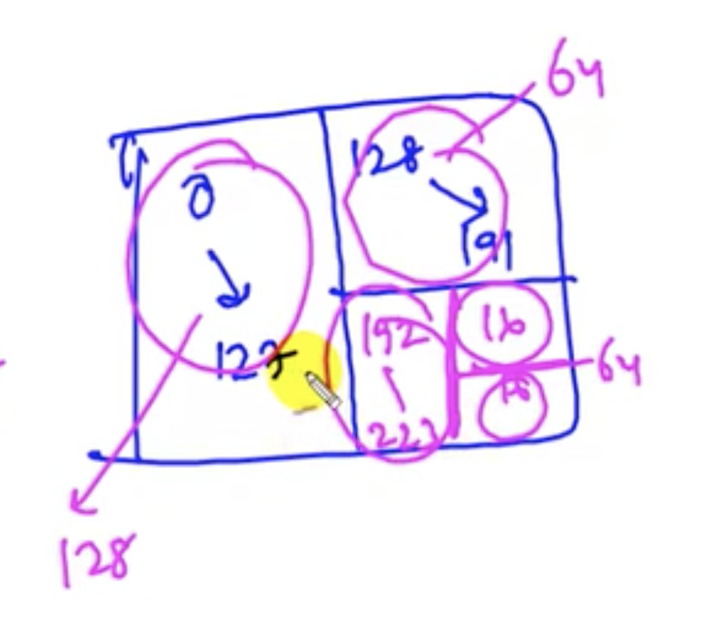
Illustration of above VLSM subnetting
4.3 Subnetting-VLSM: VLSM C-class - shortcut
As seen from the previous chapter, the network sizes of each subnet in VLSM could or could not be the same as one another.
Let us have the same example from the previous chapter:
branch 1 with 100 hosts
branch 2 with 40 hosts
branch 3 with 20 hosts
branch 4 with 10 hosts
Let us do the shortcut method.
1. Get # host bits for branch 1
2^h -2 = 2^7 - 2 >= 100
2. Get the slash value for branch 1
H = 7
32 - H = 32 - 7 = /25
So the subnet mask is 255.255.255.128
3. When doing the range, don't do all the steps for the sake of simplicity, unlike the previous chapter.
Just get the # host bits for all the branches, and get the network size, and calculate fast.
All you need to know is # host bits, network size and the slash value and calculate the range in order of different hosts.
4.4 Subnetting-VLSM: VLSM B-class
Example requirements are:
A. 4000
B. 1000
C. 500
D. 200 hosts.
The IP addresses belong to B-Class, for example 172.16.0.0.
1. Get # host bits for each subnet and # of 'blocks' (from .0 to .255) needed to comprise the subnet.
A. 2^h -2 = 2^12 - 2 = 4094 >= 4000. 4096/256 = 16 blocks needed
B. 2^10 - 2 = 1024 - 2 >= 1000. 1024/256 = 4 blocks
C. 2^9 - 2 >= 512 - 2 >= 500. 512/256 = 2 blocks
D. 2^8 - 2 >= 256 - 2 >= 200 . 256/256 = 1 block
2. Get the slash value for each subnet
A. h = 12. N = 32-12 = /20
B. h = 10. N = 32-10 = /22
C. h = 9. N = 32-9 = /23
D. h = 8. N = 32-8 = /24
3. Get the ranges with the information found
A: [172.16.0.0/20, 172.16.15.255/20]
B: [172.16.16.0/22, 172.16.19.255/22]
C: [172.16.20.0/23, 172.16.21.255/23]
D: [172.16.22.0/24, 172.16.22.255/24]
As seen, the increment of IP addresses entirely depend on the size of the network.
- for N (=network size or requirement) <= 128, X.X.X.[this portion] is incremented.
- for N (=network size or requirement) >= 256, X.X.[this portion].X is incremented (this is the case for the example covered in this chapter).
- for N (=network size or requirement) >= 65536, X.[this portion].X.X is incremented because the last two portions are not sufficient to support equal to or greater than 65536 addresses.
5.1 Subnetting questions (1)
210.10.10.145/26
You've got this IP address and the slash value.
Find:
You've got this IP address and the slash value.
Find:
- The subnet mask: look at /26. This means 7= 8 8 8 2 bits. So it's 255.255.255.192
- # hosts in subnet (# valid addresses): 2^(# host bits) - 2 = network size = 2^6 - 2 = 64 - 2 = 62
- # subnets = 2^converted network bits = 2^2 = 4
- Size of the network: 2^h = 2^6 = 64
- Range:
- 0-63
- 64-127
- 128-191 -> This is where the given IP address falls into.
- 192-255
- Network ID: 210.10.10.128/26
- Broadcast ID: 210.10.10.191/26
5.2 Subnetting questions (2)
195.10.10.194/28
Find:
Find:
- Subnet mask: 8 8 8 4 bits. So it's 255.255.255.240
- # hosts / subnet: 2^h - 2 = 2^4 -2 = 14
- # subnets = 2^converted network bits = 2^4 = 16
- Size of the network = 2^h = 2^4 = 16
- Range (needed in order to find out the network ID and the broadcast ID):
- 0
- 16
- 32
- 48
- 64
- 80
- 96
- 112
- 128
- 144-159
- 160-175
- 176-191
- 192-207 -> This is where the given IP address belongs to
- 208-223
- 224-239
- 240-255
- Network ID: 195.10.10.192
- Broadcast ID: 195.10.10.207
5.3 Subnetting questions (3)
150.12.125.10/22
Find:
Find:
- subnet mask: 8 8 6 0 bits. 255.255.252.0
- # hosts / subnet: 2^h - 2 = 2^10 - 2 = 1022
- # subnets = 2^converted network bits = 2^6 = 64
- Size of each subnet = 2^h = 2^10 = 1024 addresses
- # of blocks needed for each subnet = 1024/256 = 4
- Range:
- (150.12.)0.0
- 4.0
- 8.0
- 12.0
- 16.0
- 20.0
- 24.0
- 28.0
- ....
- 120.0-124.255
- 124.0-127.255
- 128.0-131.255
- 132.0-135.255
- ....
- 244.0-247.255
- 248.0-251.255
- 252.0-255.255
- Network ID: 150.12.124.0
- Broadcast ID: 150.12.127.255
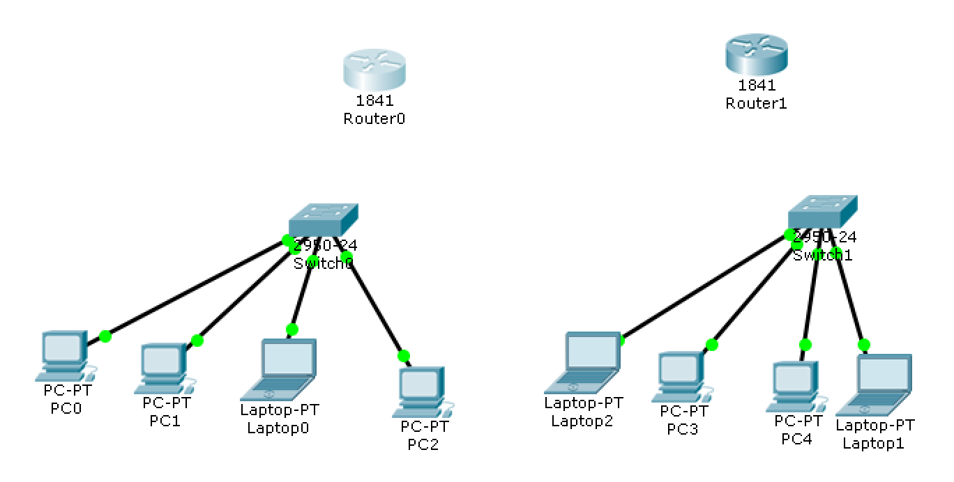
6.1 Introduction to Cisco routers: LAN connectivity
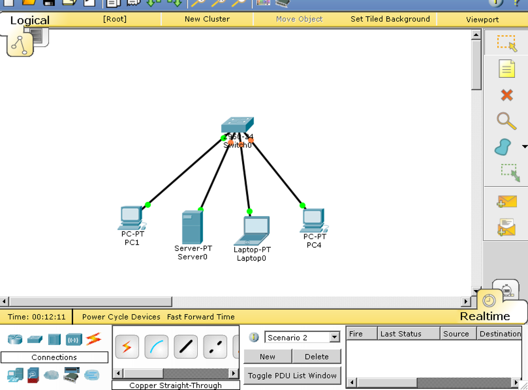
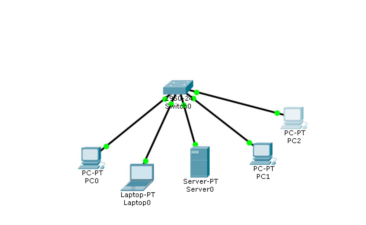
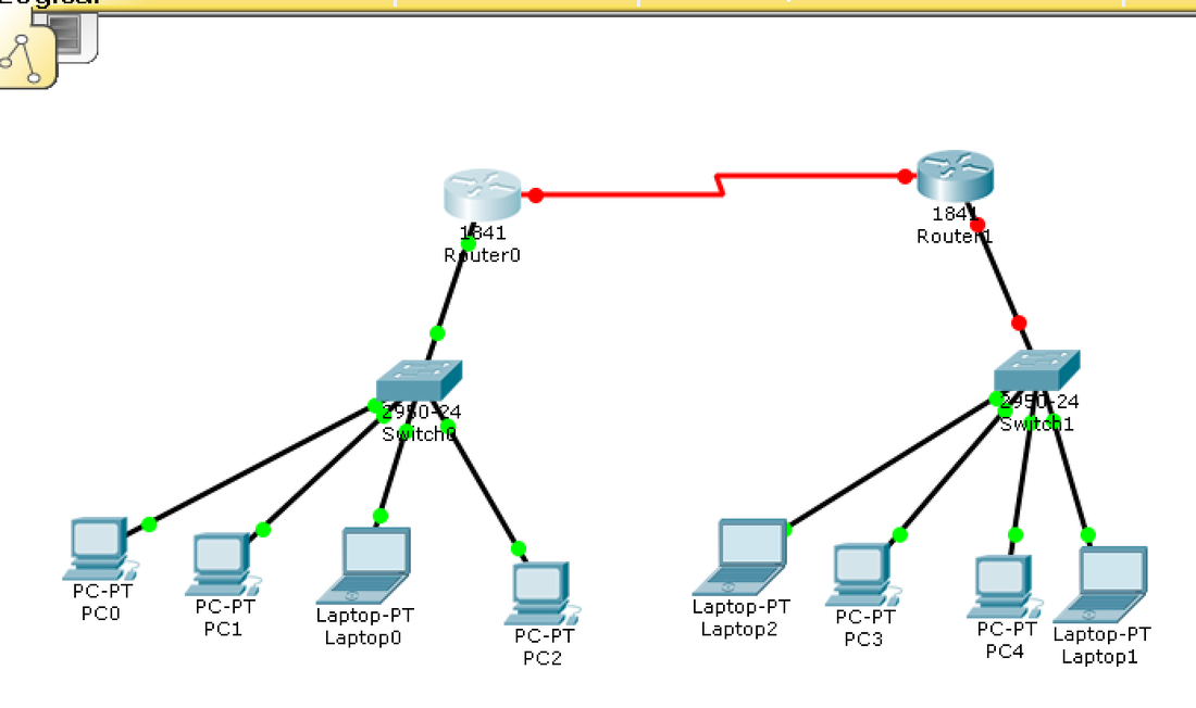
Setting up a LAN using packet tracer so that:
- 4 computers are connected in the LAN using switch
- IP addressing on all computers are configured using 192.168.1.0/24 network
- Connectivity can be checked between all the computers using a command
Launch packet tracer.
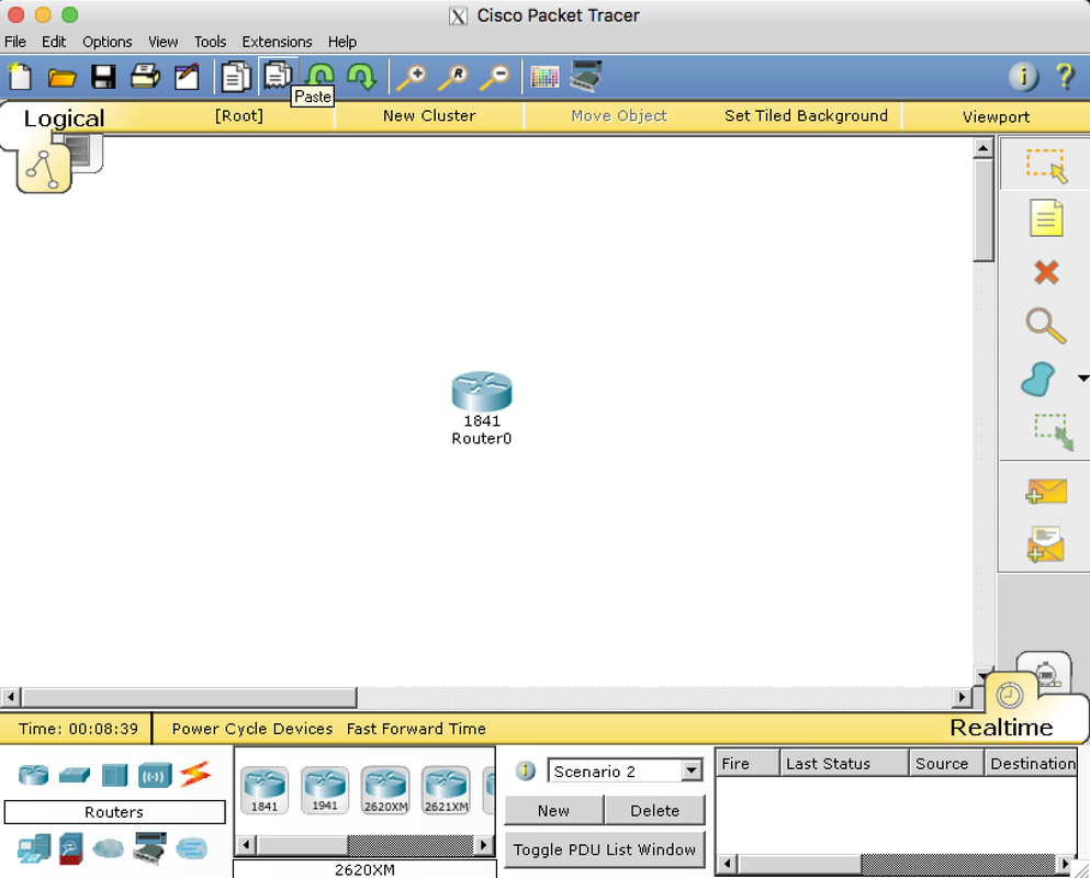
Add one switch and different types of end devices.
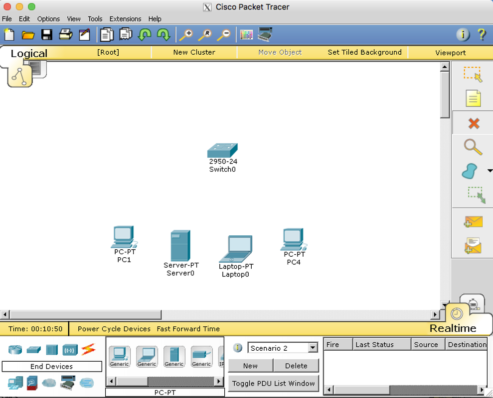
add cables:
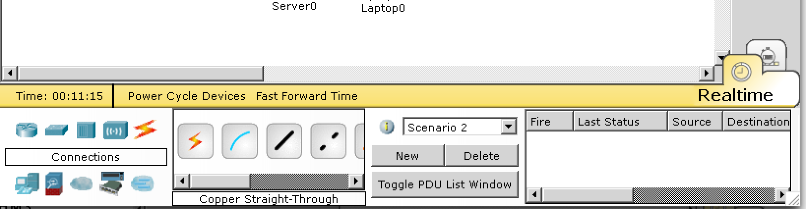
for now, just use any port (ex. first port for switch) and fastEthernet0 for end devices with copper straight-through cable.
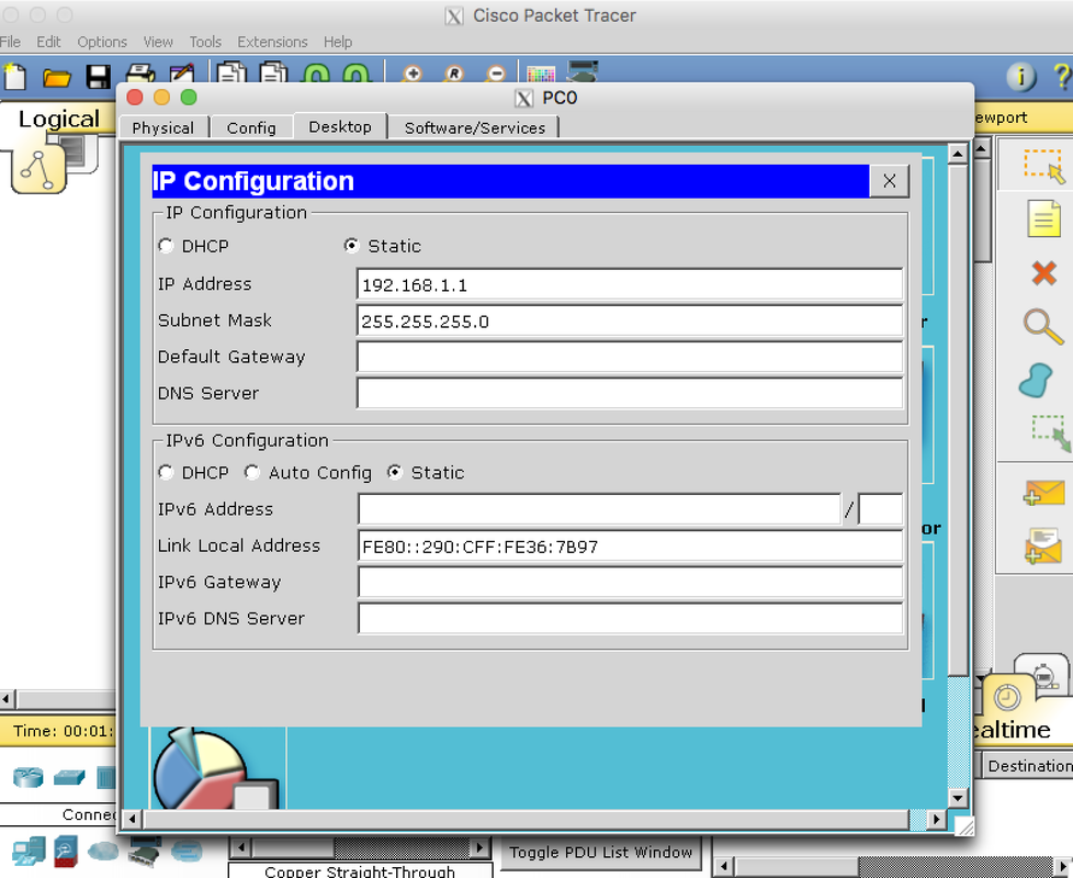
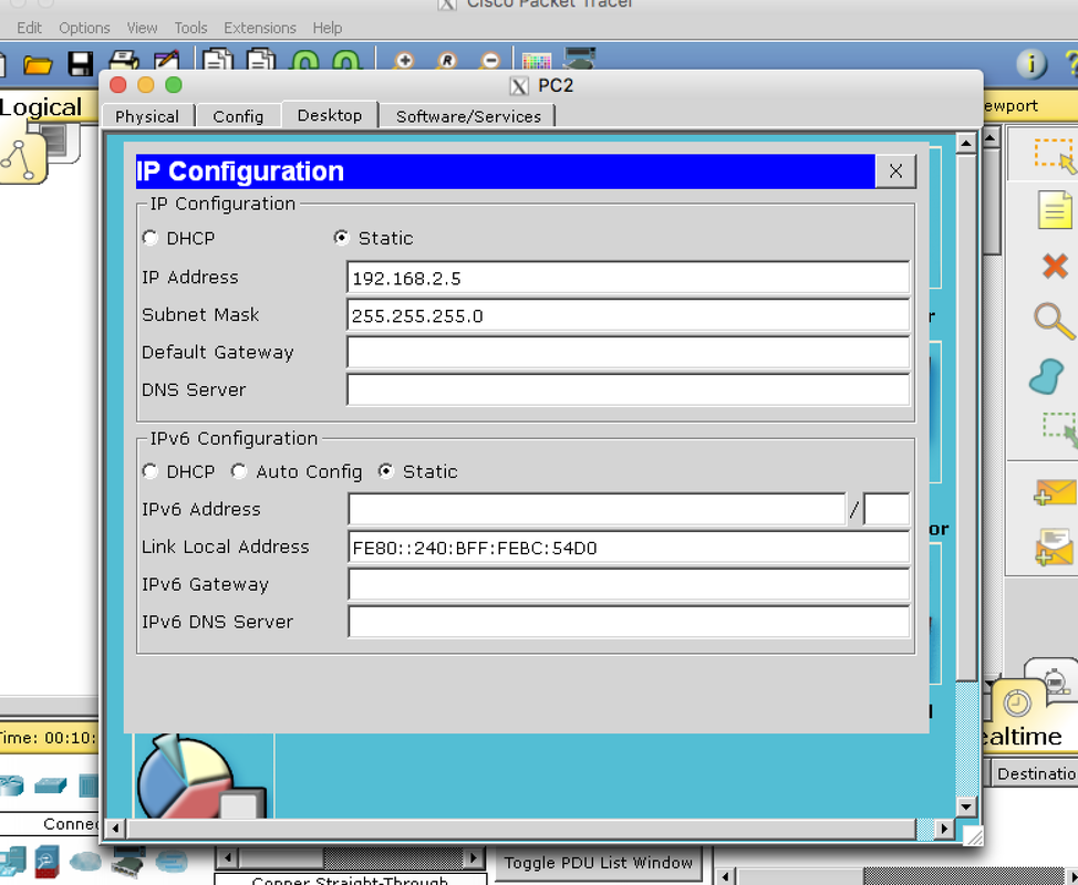
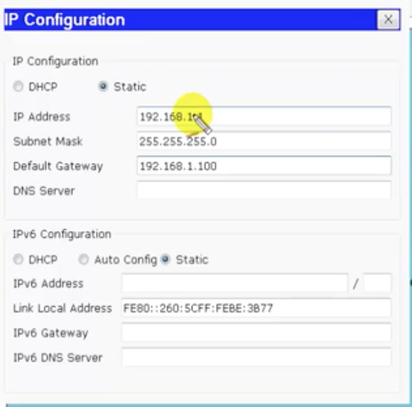
How to assign IP addresses(four devices, each getting .1, .2, .3, and .4) using 192.168.1.0/24:
1. click on the PC (leftmost PC icon connected to the switch) and click on desktop -> IP configuration input the IP address 192.168.1.1 (the subnet mask is filled in automatically).
2. Do the same for the rest of the end devices and fill out respective IP addresses.
1. click on the PC (leftmost PC icon connected to the switch) and click on desktop -> IP configuration input the IP address 192.168.1.1 (the subnet mask is filled in automatically).
2. Do the same for the rest of the end devices and fill out respective IP addresses.
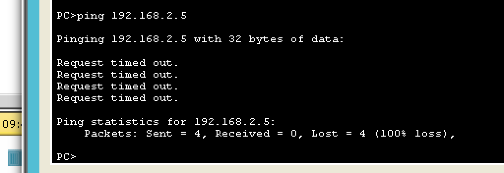
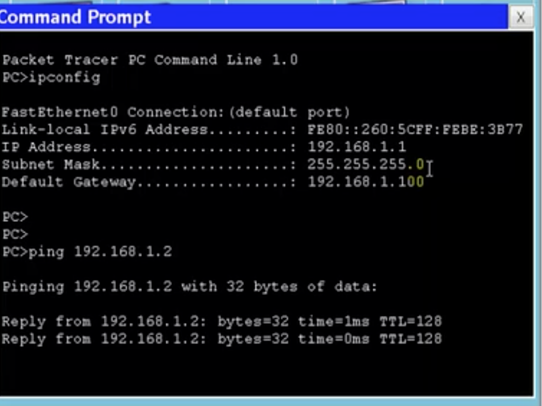
3. Test the connectivity. Open up the command prompt and type ipconfig and ping [another IP address in the server] to check the connection between the end devices in the network. If the replies come back, that means they are connected through the server.
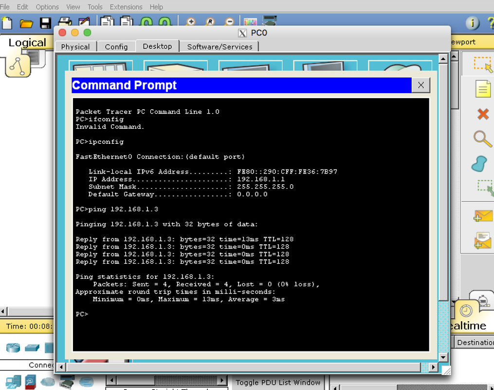
if you try to make another computer and connect that as well to the switch but put it into different network (for example by assigning it an IP address of 192.168.2.5), the ping command will only report 100% loss in the packets sent.
|
|
|
6.2 Introduction to Cisco routers: Cisco routers hierarchy
Router and its functions
Router is an internetworking device used to connect two or more different networks.
Note: physical locations of different computers could be the same, but the logical location may not be.
If we want different LAN(that is, essentially, a group of computers in the same local network connected through a switch)s to talk to each other, we need a router.
2 different LANs mean they would require 2 different routers.
4 would mean 4 routers.
10 would mean 10.
and so on.
Manufacturers of routers
Cisco's hierarchical design model
1. Access layer router
low cost, processing capabilities and # of ports (leftmost in the picture)
2. Distribution layer router
medium (middle)
3. Core layer router
high (rightmost)
Router is an internetworking device used to connect two or more different networks.
Note: physical locations of different computers could be the same, but the logical location may not be.
If we want different LAN(that is, essentially, a group of computers in the same local network connected through a switch)s to talk to each other, we need a router.
2 different LANs mean they would require 2 different routers.
4 would mean 4 routers.
10 would mean 10.
and so on.
Manufacturers of routers
- Cisco
- Nortel
- Multicom
- Cyclades
- Juniper
- Dlink
- Linksys
- 3Com
- ...
Cisco's hierarchical design model
1. Access layer router
low cost, processing capabilities and # of ports (leftmost in the picture)
2. Distribution layer router
medium (middle)
3. Core layer router
high (rightmost)
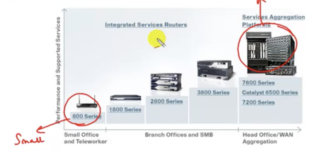
Deciding which router to choose
Typically, small branches are connected to medium sized branch offices (perhaps regional offices) and these regional offices are connected to the HQ. This happens because of the limitation of WAN: for each small branches, you need to connect them one by one if you do not connect them in this tree-like structure.
Typically, small branches are connected to medium sized branch offices (perhaps regional offices) and these regional offices are connected to the HQ. This happens because of the limitation of WAN: for each small branches, you need to connect them one by one if you do not connect them in this tree-like structure.
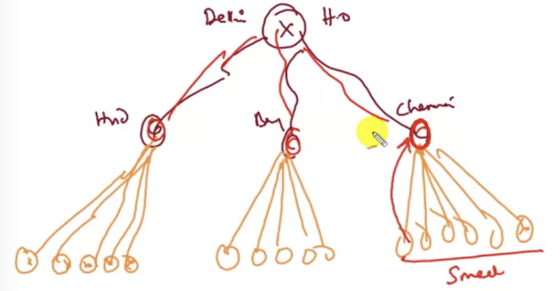
So what to use for each office? If any user in the small office wants to talk to another user in region, the traffic must go through the HQ. This means as we go up from the bottom to the top of the tree, the amount of traffic to be managed gets a lot larger. So HQ will carry the biggest traffic.
So for the offices close to the bottom of the tree: use access layer router.
For the offices located around the middle of the tree: use distribution layer router.
for the offices at the top: use core layer router.
So for the offices close to the bottom of the tree: use access layer router.
For the offices located around the middle of the tree: use distribution layer router.
for the offices at the top: use core layer router.
Router series
Access layer: 800, 100, 1600, 1700, 1800, 2500
Distribution layer: 2600, 3200, 3600, 3700, 3800
Core layer: 6400, 7200, 7300, 7400, 7500, 7600, 10000, 12000
Across different layers, CLI would be a bit different.
Access layer: 800, 100, 1600, 1700, 1800, 2500
Distribution layer: 2600, 3200, 3600, 3700, 3800
Core layer: 6400, 7200, 7300, 7400, 7500, 7600, 10000, 12000
Across different layers, CLI would be a bit different.
6.3 Introduction to Cisco routers: External ports of Cisco routers
Router classification
1. Fixed router
2. Modular router
External ports of a router
LAN ports (RJ45)
Typically LAN port is the FastEthernet Ports (with different speeds based on different routers).
1. Fixed router
- All ports are integrated on motherboard (no slots)
- cannot add/remove/upgrade interfaces.
- 2500, 800 series.
2. Modular router
- Has slots where cards (with extra ports) can be added
- Distribution and core layer routers are in this category.
- 1600, 1700, 1800, 2600, 2800, 3600, 3700 series.
External ports of a router
- At the back of a router, there are many ports that could be categorized into three different types: LAN, WAN and admin ports.
- LAN: this related to the connection between the router and the switch.
- WAN: this is related to the connection between the routers.
- admin port: .
LAN ports (RJ45)
Typically LAN port is the FastEthernet Ports (with different speeds based on different routers).
- Ethernet: 10 Mbps
- Fast Ethernet: 100 Mbps
- Gig Ethernet: 1000 Mbps (Megabits per second)
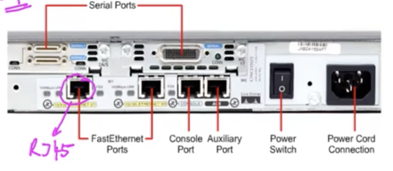
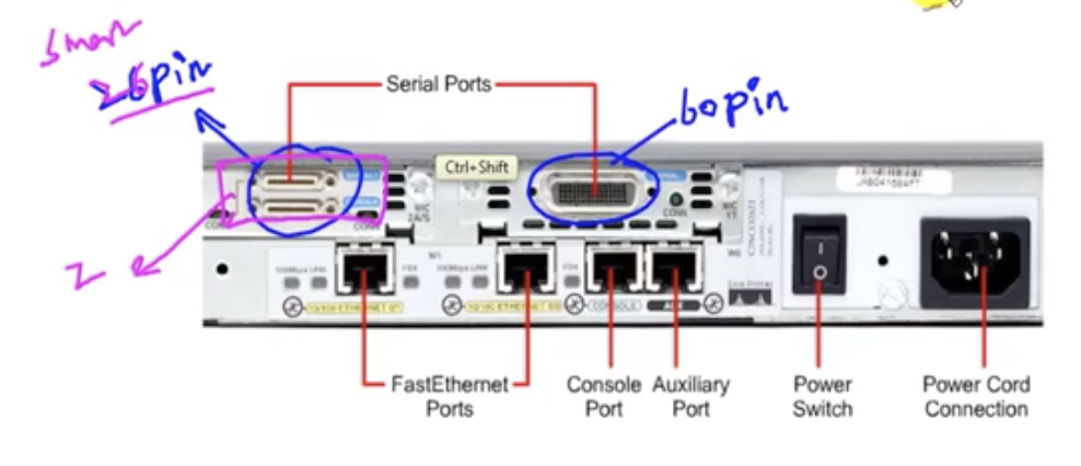
WAN ports
- This is the serial port.
- It can be either 26 pin (smarter) or 60 pin (older). For 26 pin, you can have two WANs (means 2 T).
- The number of ports depend on the model.
Admin ports
They do not carry any traffics. They carry admin's commands. To configure a router, you need to connect the router with a computer through the console port.
They do not carry any traffics. They carry admin's commands. To configure a router, you need to connect the router with a computer through the console port.
- Console port(for local admin station)
- Auxiliary port (for remote admin station)
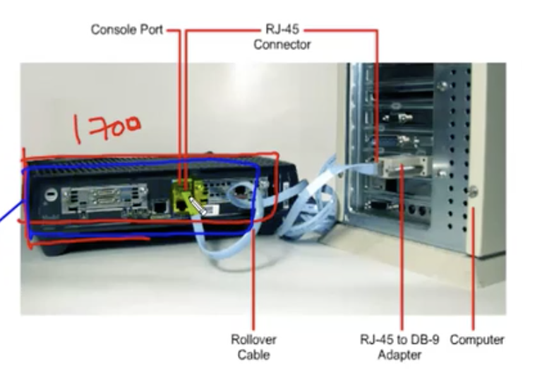
console connection
After the configuration, we can view what the router is doing on the computer.
Remote admin station
The router and the remote admin station are connected through a set of two dial-up modems and a telecom line.
The router and the remote admin station are connected through a set of two dial-up modems and a telecom line.
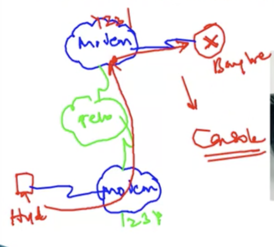
Drawbacks
- Not reliable
- No high-speed connection, as it is just a dial-up connection.
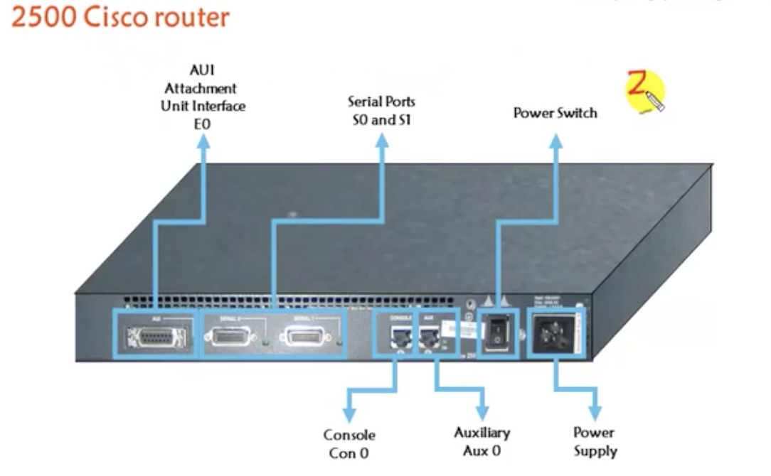
just another model of a router. Attachment Unit Interface (AUI) requires 15 pin connecter, and it only supports Ethernet only. We need a converter (15 pin converter) known as a transceiver to RJ45.
AUI
- AUI pin configuration is 15 pin female.
- It is known as Ethernet port or LAN port or default gateway.
- It is used for connecting LAN to the router.
- Transceiver is used for converting 8 wires to 15 wires (from RJ45 to 15 pin converter)
- Only some particular models have this.
6.4 Introduction to Cisco routers: Internal components
- POST: turns on the device. Checks the hardware
- ROM: loads the bootstrap programs (instructs how IOS should be loaded) and searches for the IOS-Internetwork Operating System (Flash/TFTP/ROM)
- FLASH: stores IOS
- NV(Non-Volatile)RAM: Stores configurations (permanent) = startup-config
- RAM: Stores configurations (temporary) = running-config.
When a router boots, it goes from POST to FLASH in above order. Then, the flash will load IOS onto RAM. Once IOS is loaded, configurations in NVRAM is loaded onto RAM. If you make any changes, it will be saved back to NVRAM to be saved permanently.
7.1 Basic commands: console connectivity
1. Do console connection (dotted line on packet tracer)
2. Use terminal emulation programs to see the CLI of the router. So the emulation program will enable us to perform operations on the router and check what's happening. Software available for this include:
So open up the packet tracer.
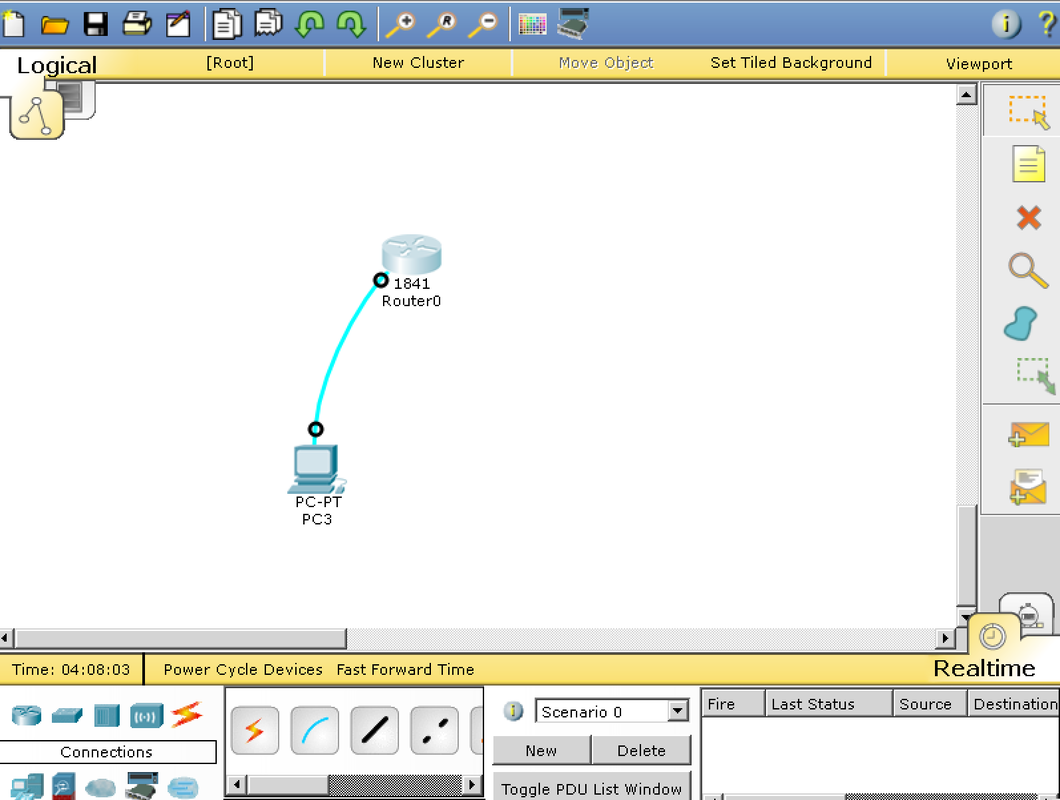
1. Place one router
2. Place one computer
3. Click on the router, and click on the option 'console'.
4. Click on the computer and click on the option 'RS232'.
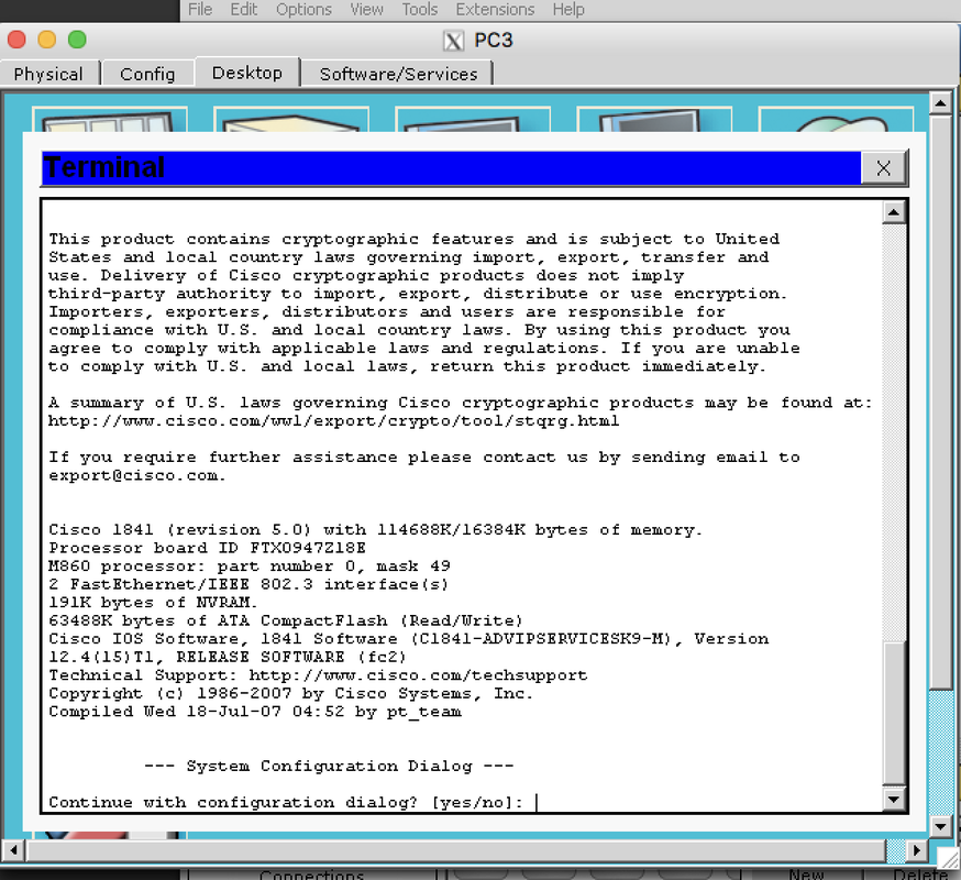
5. The command line can be seen on both the PC and the router. Just go onto each of them and see the 'terminal' for the PC and 'CLI' for the router. The same thing can be viewed.
2. Use terminal emulation programs to see the CLI of the router. So the emulation program will enable us to perform operations on the router and check what's happening. Software available for this include:
- HyperTerminal
- PuTTY
- Tera Term
- SecureCRT
- OS X Terminal
So open up the packet tracer.
1. Place one router
2. Place one computer
3. Click on the router, and click on the option 'console'.
4. Click on the computer and click on the option 'RS232'.
5. The command line can be seen on both the PC and the router. Just go onto each of them and see the 'terminal' for the PC and 'CLI' for the router. The same thing can be viewed.
|
|
|
7.2 Basic commands: User mode - user & privilege mode
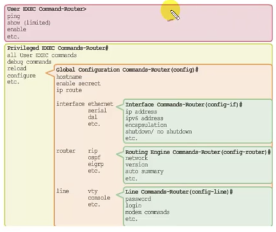
IOS Mode Hierarchical Structure
Modes on Cisco Routers
As the picture shows, the Cisco routers have different levels or 'modes' of commands. These include:
As the picture shows, the Cisco routers have different levels or 'modes' of commands. These include:
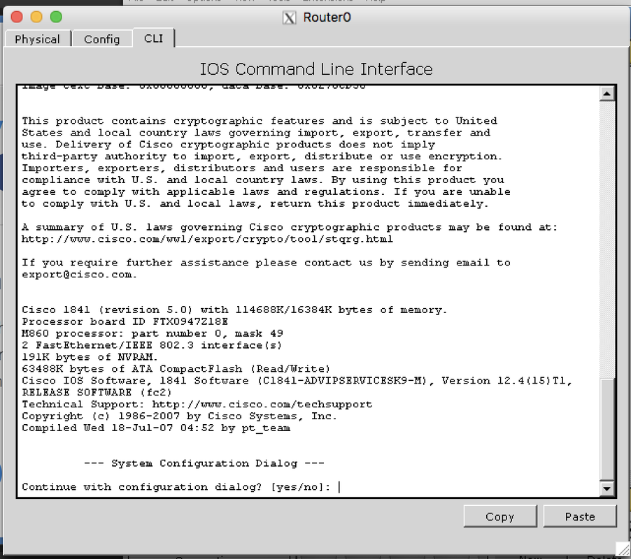
- Setup mode: if NVRAM is blank. Whenever the router boots, the configuration is loaded from NVRAM to RAM. If there's nothing configured in NVRAM, you will enter the setup mode. This happens when you have a new router or when you want to configure the router upon start.
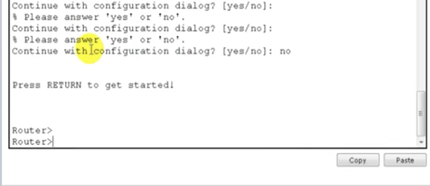
Rejecting setup mode, thus officially starting the router
- User mode: the mode you get into after launch the CLI (and after rejecting the setup mode) is the user mode. It only allows you to do only basic monitoring commands. These include 'show flash', 'show version' and 'sh ip interface brief', 'ping [IP address]', 'traceroute [IP address]'.
CLI for user mode
- Privileged mode: allows you to do complete monitoring and some troubleshooting. Can enter this mode by typing in 'enable' in CLI. The '>' sign gets changed to '#' in this mode.
CLI for privilege mode
Note: if you forget commands, you can place a question mark after some command, like: sh?.
This will show possible commands starting with 'sh'. Typing a tab will autocomplete the letter (just like in bash terminal)
This will show possible commands starting with 'sh'. Typing a tab will autocomplete the letter (just like in bash terminal)
Other modes include:
- Global configuration mode: All configurations that affects the router globally.
- Interface mode: configurations done on the specific interface
- Rommon mode: reverting password
7.3 Basic commands: Global configuration mode - Line passwords
In user mode or privilege mode, you cannot make changes. To do so, you have to enter global configuration mode. By default, a router's name is named as 'router'. To avoid naming conflicts in a network with multiple routers or switches (that are named as 'switch'), you need to change the hostname.
Hostnames allow devices to be identified by network administrators over a network or the Internet.
Hostnames allow devices to be identified by network administrators over a network or the Internet.
Configuring the host name
Assigning passwords: why need a password at all?
Passwords restrict any users from accessing my router. By default, there is no password for a router. So you want to secure the router with a password. There are largely three ways to connect the router to a computer:
1. Console
2. Auxiliary
Passwords restrict any users from accessing my router. By default, there is no password for a router. So you want to secure the router with a password. There are largely three ways to connect the router to a computer:
1. Console
2. Auxiliary
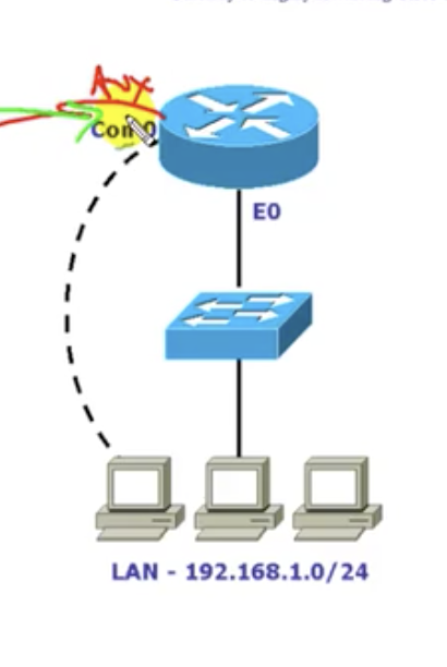
console connection (dashed line).
3. VTY line (telnet)
Say you've got two LANs for different offices. What you want to do is to configure something on the router in the office that your LAN does not belong to. You want to access that router remotely.
What you can do is:
1. Go onto CLI and telnet [IP address].
2. It is going to ask for a password
3. Then the device you are using will be connected to the router.
It is not an actual connection. It is a virtual connection.
And the prerequisites for this telnet connection are:
1. The router and the device on which you are managing the CLI must be connected with each other.
2. You have to know the IP address of the router to be configured.
3. You have to know the password of the router.
Telnet is the most common way of accessing a router, but only with these prerequisites.
Assigning the passwords: how
1. Assigning console password
1. Assigning console password
2. Assigning auxiliary password
3. Assigning telnet password
4. Verifying the configured passwords:
do it with show running-config.
do it with show running-config.
7.4 Basic commands: password for 'enable' command - saving configurations
You can configure the CLI to prompt a password when a user types 'enable'. There are two ways of doing it (both must be done in a config mode, which you can enter by typing configure terminal):
1. enable password <password>
2. enable secret <password>
1. enable password <password>
2. enable secret <password>
So after exiting everything, the first password prompt is for the console password.
The second password prompt that you get after typing 'enable' is the enable password.
The second password prompt that you get after typing 'enable' is the enable password.
See that the secret password is encrypted, but the password for the first method is not.
What if you configure both passwords?
the preferred password will be the secret (encrypted) password only. The clear text password will not be accepted.
the preferred password will be the secret (encrypted) password only. The clear text password will not be accepted.
Encrypt password display when you do 'show running-config' with 'service password-encryption' command:
Saving the configuration
Router# copy running-config startup-config
// save the running configuration into the startup-configuration which is supposedly empty
OR
Router# write memory
OR
Router# write
if you don't do the above step, the router will forget the configurations made because the current configurations are not in NVRAM but RAM without the above commands.
Erase all configurations
Router#erase startup-config
you can check with the new changes made with 'reload' command which reboots the router.
8.1 WAN Connectivity: Basics
LAN-to-LAN connections are built using WAN (Wide Area Network). But how does it really work? What are the different types of WAN connections we need to use? We need to contact the service provider in order to connect the router to another router.
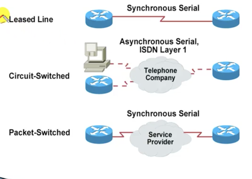
Different types of WAN connections
1. Leased line
2. Circuit-switched:
3. Packet-switched
Different types of WAN connections
1. Leased line
2. Circuit-switched:
3. Packet-switched
Modern WAN connections
- MPLS
- Metro Ethernet
- Virtual Private Network (VPN)
- DSL
- Cable
- VSAT
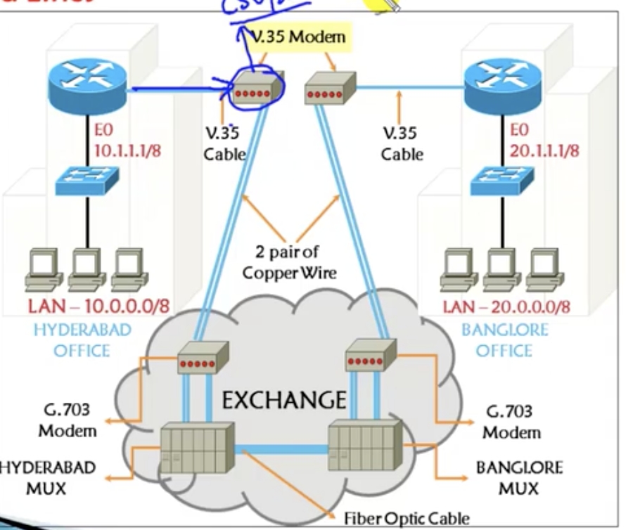
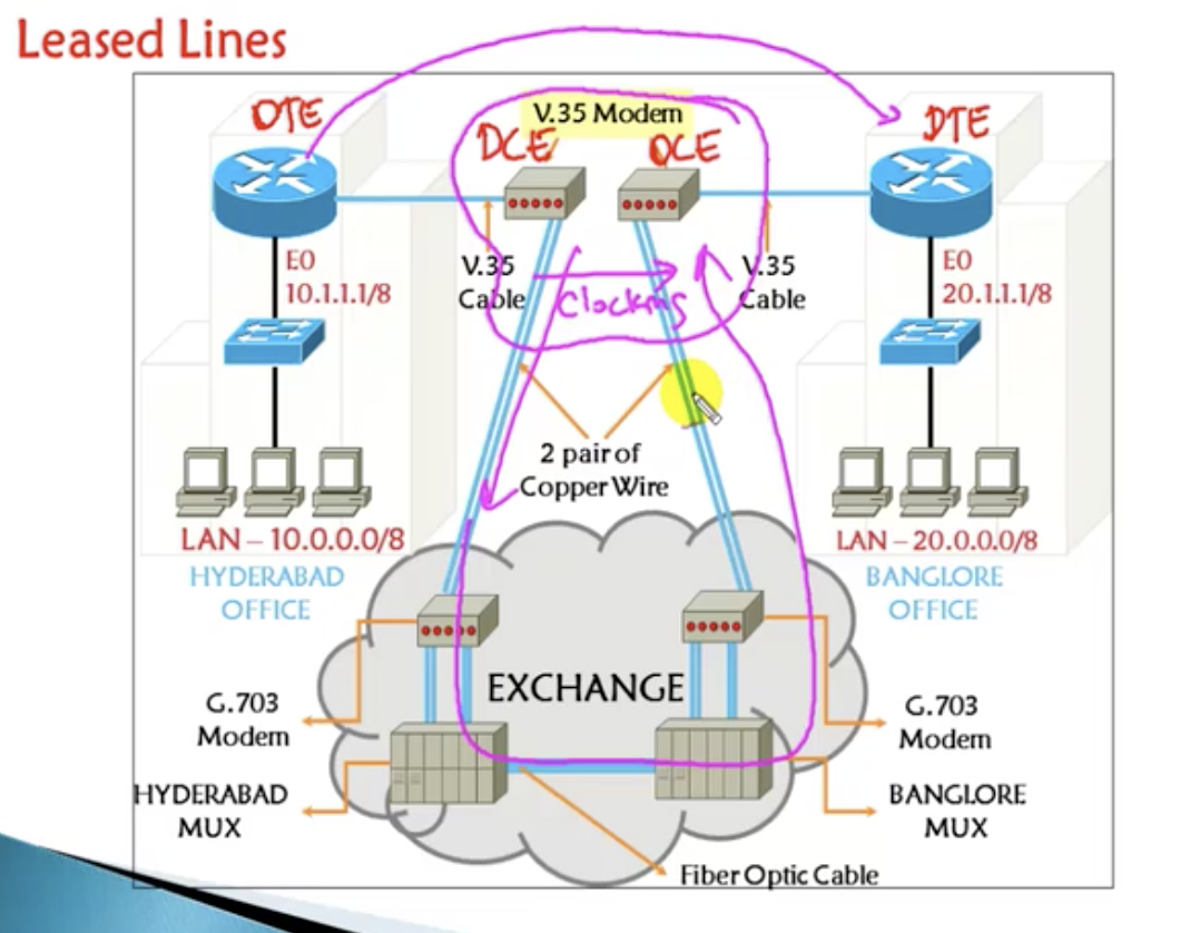
Leased line
- You've got your LAN and you wanna connect it to another LAN so that the users connected to each of these different LANs can talk to each other.
- Then you need to contact the service provider who is going to provide the line that connects the routers (leased line connection).
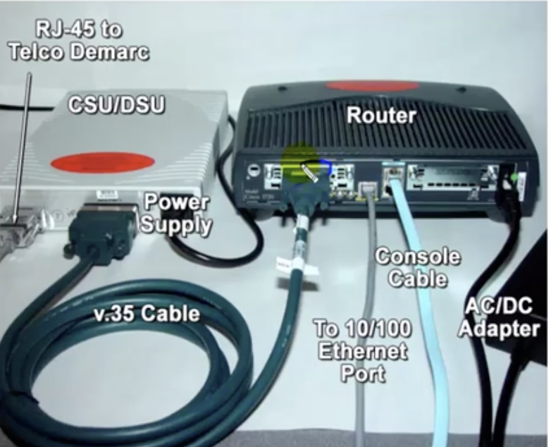
- In the leased line connection,
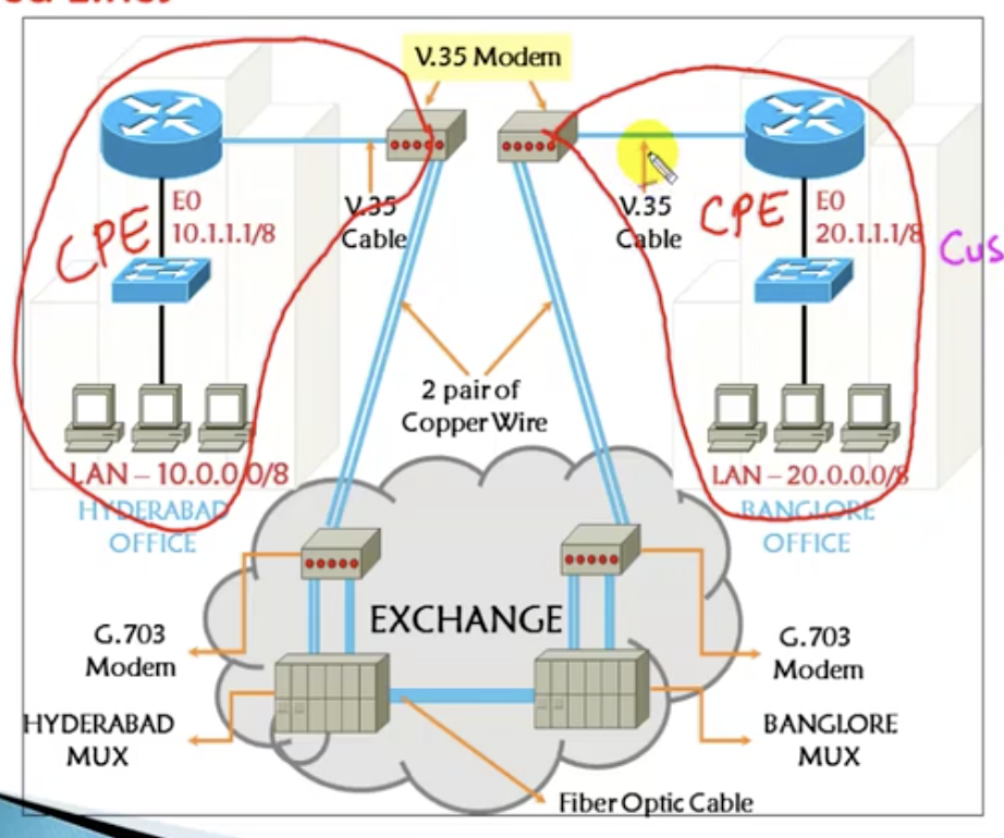
- Router 1 connects to the V.35 Modem called CSV/DSV modem. This is placed at the same location as the router. Typically it is provided by the service provider. The v.35 cable will connect CSU/DSU to the router.
- The portion of the diagram that includes the computers that belong to the switch and one router and finally the V.35 Modem is called customer-premises equipment. Anything that goes into this portion is up to the customer to manage and fix.
- The service provider will use copper wires to connect to a long-distance modem in the exchange centre. This is going to be connected to a multiplexer. MUX is going to take multiple signals (from other customers as well) and differentiate each of them according to where they belong to. This applies the same for the other side of the diagram. However this part is not of our concern.
- Finally the multiplexers are connected through the fibre optic cable.
|
|
|
DTE and DCE
DTE is a Dialup connection. Your device (DTE = Data Termination Equipment) is connected to the modem (DCE = Data communication equipment) which will allow you to send the data to a remote location through telecom and then the Internet. The computer at the end will only accept clock signals.
DTE is a Dialup connection. Your device (DTE = Data Termination Equipment) is connected to the modem (DCE = Data communication equipment) which will allow you to send the data to a remote location through telecom and then the Internet. The computer at the end will only accept clock signals.
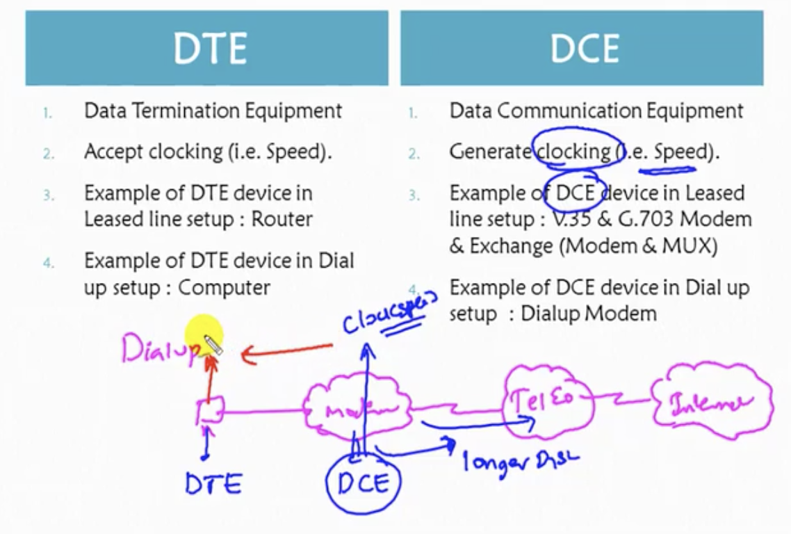
The same kind of setup as the above diagram applies to the leased line setup we saw in the previous X 2 diagram.
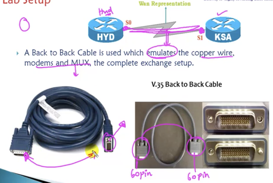
Lab setup
Back to back cable is used to emulate to copper wire, modems and MUX (basically the complete exchange setup) to just represent the WAN connection. We do not use the real things in the lab scenarios.
Back to back cable is used to emulate to copper wire, modems and MUX (basically the complete exchange setup) to just represent the WAN connection. We do not use the real things in the lab scenarios.
8.2 WAN Connectivity: Rules to assign IP address
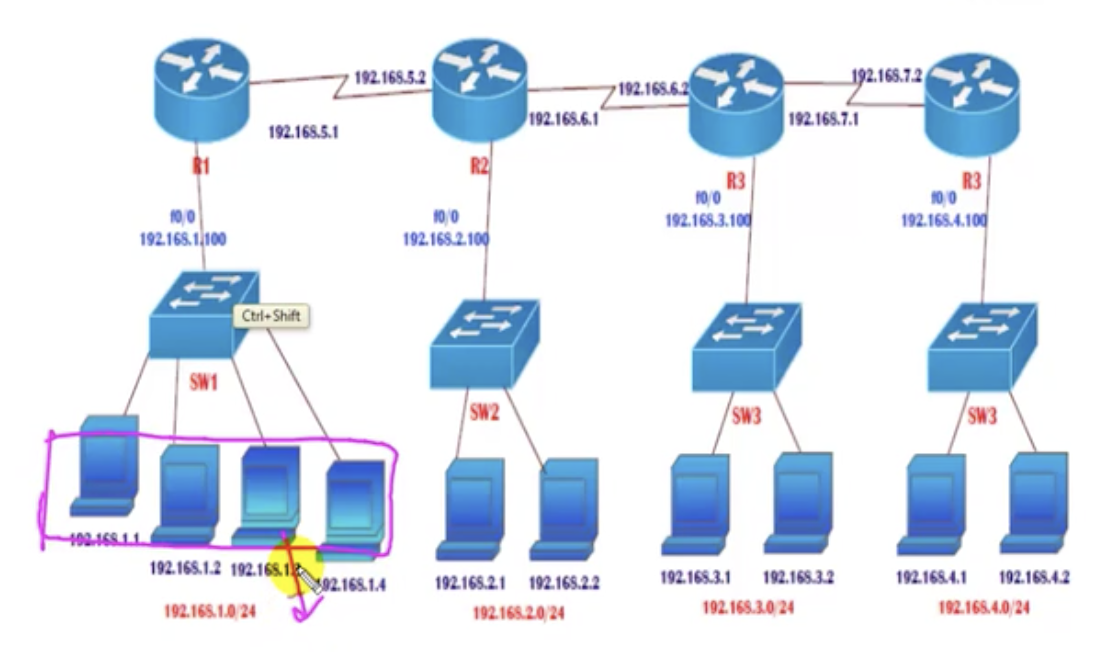
- You have to assign an IP address to each device in the network. But how? It depends on the number of interfaces.
- For R1 and R4, they are connected to two interfaces (SW1 and R2), so it needs to have two IP addresses.
- For R2 and R3, three IP addresses.
- All the LANs and WANs should be in different networks (or should not repeat the same networks). For example branch A (leftmost in the diagram, boxed in pink) is assigned with the network 192.168.1.0/24. Then this network (ID) cannot be taken anywhere in other connected branches or other LANs OR WANs. Otherwise confusion happens.
- Each set of router Ethernet IP (Router's IP address to connect to the switch and end user devices) and the LAN network (the switch and end-user devices) should be in the same network. For example, the first IP address of R1 (=192.168.1.100) must be in the same network as the computers in branch A (network ID = 192.168.1.0/24)
- Both interfaces of router facing each other should be in the same network. The routers facing each other in above diagram must be in the same network (of course they use different subnet to connect to each other with different IP addresses. For example in R2, it has 192.168.5.2 to connect to R1 and 192.168.6.1 to connect to R3.).
- All the interfaces of routers should be in different networks. This rule is going to be satisfied once the rest of the rules are satisfied. For example, R2 has 192.168.5.2, 192.168.2.100, and 182.168.6.1. They are all in different networks even though these IP addresses are coming from a single router.
8.3 WAN Connectivity: IP address configuration
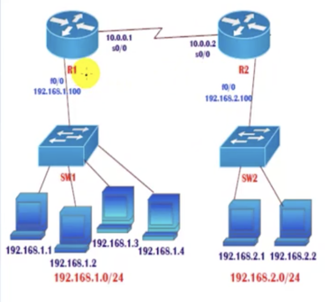
How can we design the above configuration?
1. Design the topology
1. Design the topology
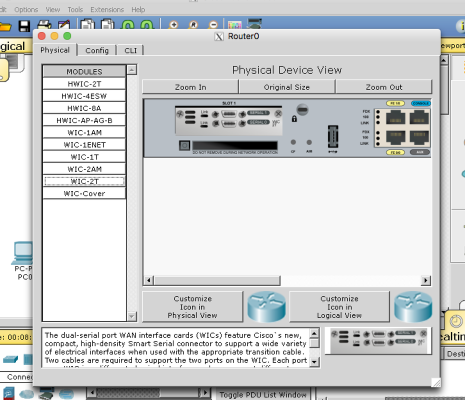
- Use 'straight cable's to connect between a router and a switch and also between a switch and end-user devices.
- Use 'back-to-back cable' (Serial DCE) to connect between routers. But there is no serial port. We need to add a card to the router. Choose WIC-2T (means two serial ports) card to put into the card slot. Ensure the router power is off before putting the card in. Otherwise you cannot.
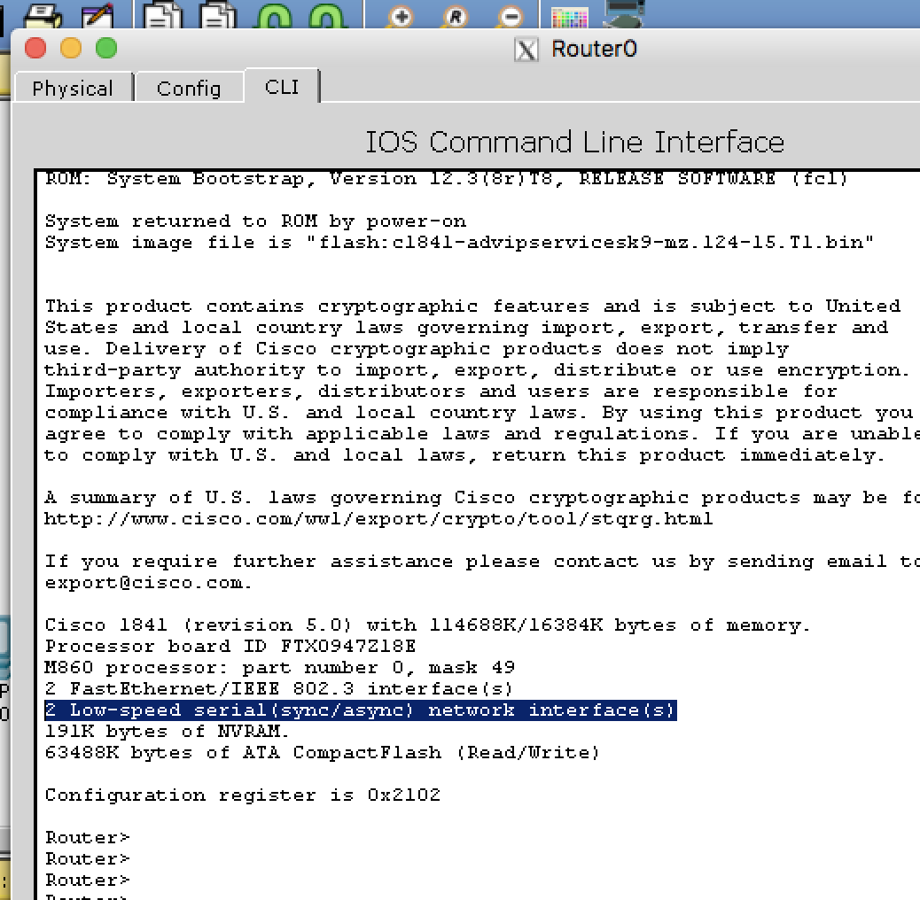
- Check that the cards are correctly placed into the router by typing show version on CLI of the router.
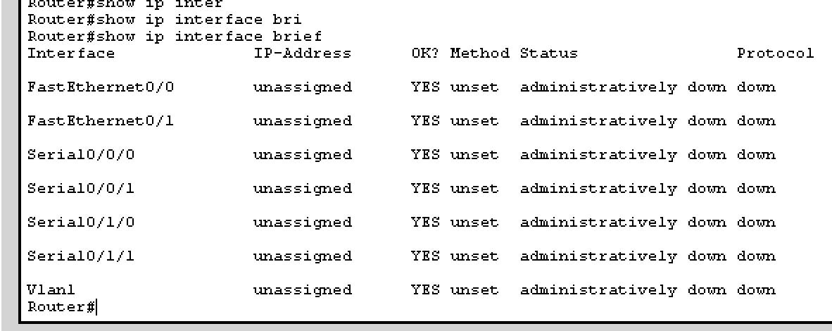
- Alternatively, type show ip int(interface) brief to check it. Understanding the numbering is also important.
- as of now, it does not matter which port you connect to for each device. Just make sure the are all FastEthernet. And for routers, use FastEthernet0/0.
|
|
|
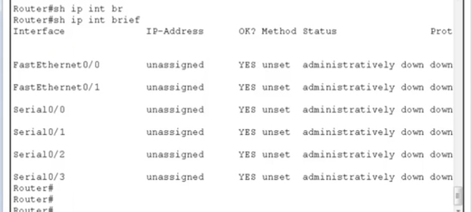
"In Serial 0/0", the first number represents the slot number, and the following number represents port number.
In a different router (on mine for example), the numbering may be a bit different. Some routers have the main slot (numbered as 0) and subslots numbered from 0 to n, and they also have the port number. So it goes like: [slot #]/[subslot #]/[port #].
2. Assign IP addresses
Make sure you know the port numbers in the routers that are used to connect to another router (for example, S0/0 or S0/1/0) because you only need to assign an IP address to that particular port. As of now, just use S0/0/0 to make it simple.
Make sure you know the port numbers in the routers that are used to connect to another router (for example, S0/0 or S0/1/0) because you only need to assign an IP address to that particular port. As of now, just use S0/0/0 to make it simple.
Commands
Hands-on
After this configuration, notice that there are now green lights on the connection between the router and the switch.
Now, you know what to do: do the same for the second router.
Then, check the WAN connection with ping command:
Now, go to individual computers and configure the IP addresses according to the given picture.
|
|
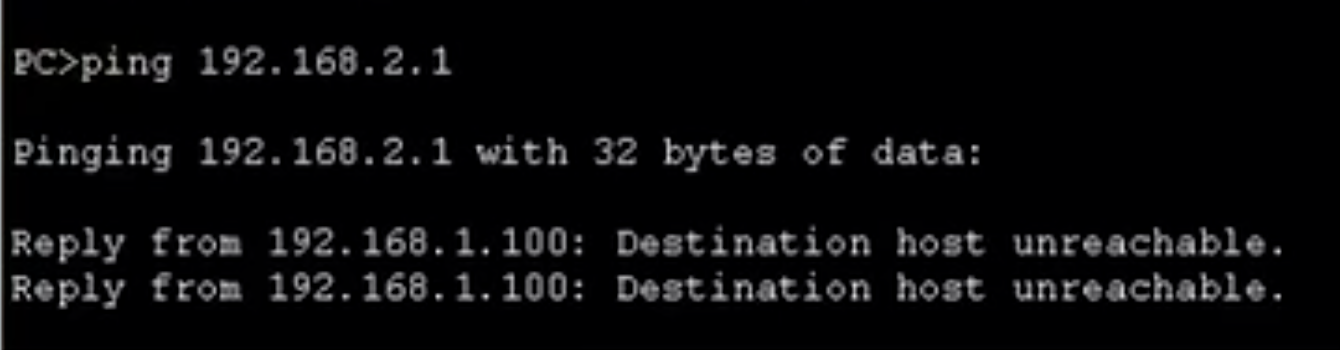
The gateway address in this case is the router's IP address in the LAN the computer belongs to, because the traffic from the computer has to go through the router to reach another computer on another LAN. you could always ping on a device to another device to check if the connection is established. However ping to an end-user device on the other LAN still does not work (picture below) because something called routing is needed.
8.4 WAN Connectivity: Troubleshooting connectivity
show ip interface brief
If you want to see the status of interfaces.
up/down means the status is ok. But if you don't see them, something's wrong.
Different connectivity statuses
1. Serial is up (physical connection), and ine protocol is up (protocol)
Possible issues:
If you want to see the status of interfaces.
up/down means the status is ok. But if you don't see them, something's wrong.
Different connectivity statuses
1. Serial is up (physical connection), and ine protocol is up (protocol)
- The connectivity is fine. You see ups and downs.
Possible issues:
- remote device is turned off
- remote port is in shutdown state (this means the remote router has to be configured)
- otherwise, there is a problem with connectivity (you need to contact the service provider)
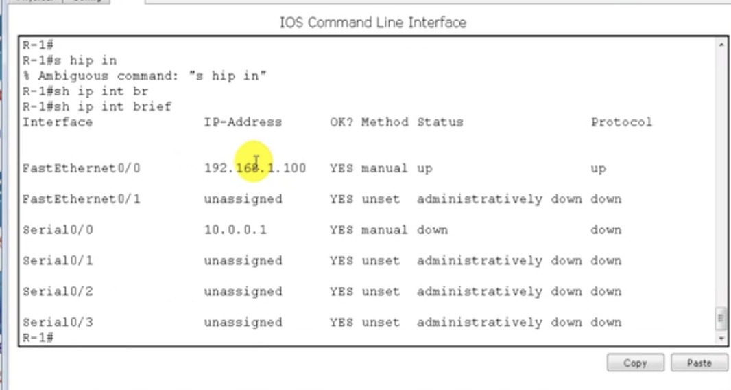
Look at Serial 0/0 to which the current router is. connected. The status and the protocol are 'down'.
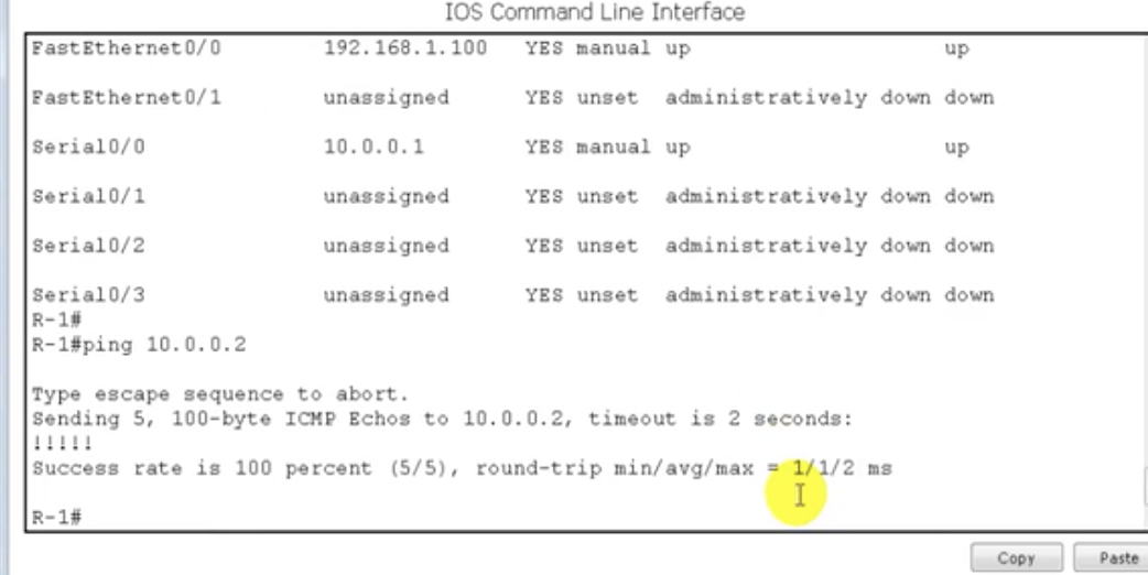
After turning on the problematic router, you can see on the router that the protocol and the status are up and therefore ping works.
3. Serial is administratively down, and line protocol is down
- Possible issue: local port (my router's port. This is not the remote port, which is the port of the router that my router is connected to) is in shutdown state
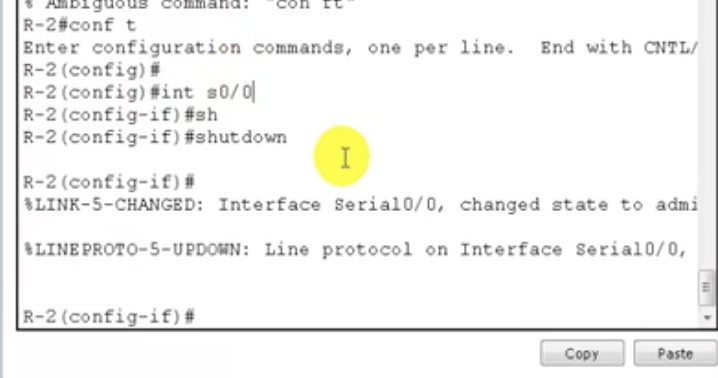
Shut down the interface on R2.
|
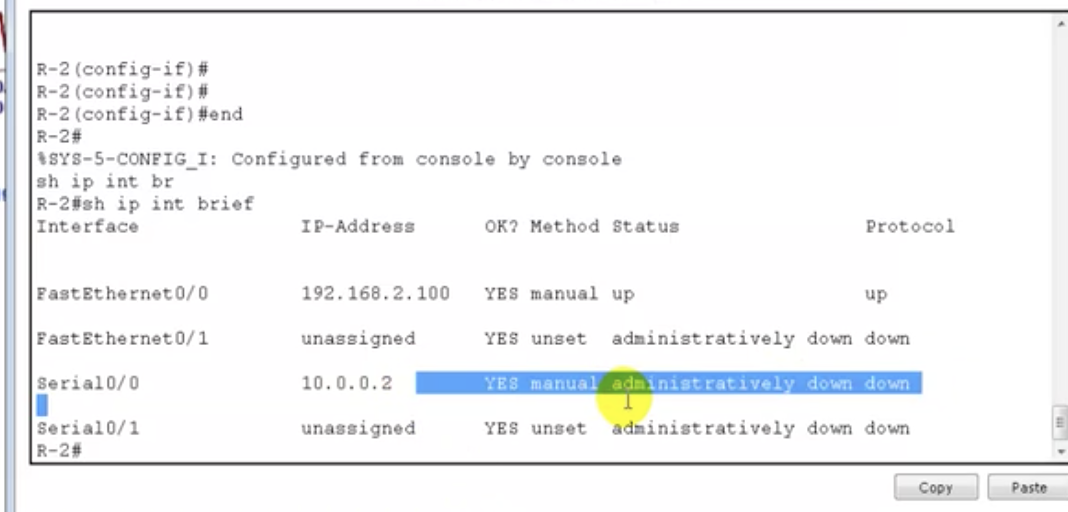
Serial 0/0 on R2 now shows 'administratively down' for status message and down for protocol.
|
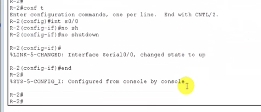
To fix the problem, enter configuration terminal and configure the interface that's shut down and type no shutdown to make it up.
|
4. Serial is up, line protocol is down
- Encapsulation mismatch (mistmatch between protocols. If you are running HDLC on one router and PPP on the other router, you are going to get up for serial and down for protocol. This means the physical connection is up, but the protocols do not match.)
- clock rate command not given on serial interface (only in lab scenario)
- if using PPP, then authentication mismatch (you can configure a password for the connection between two routers and you need to type in the password for each router. If there is a mismatch of the passwords, it's an authentication mismatch.
8.4 WAN Connectivity: WAN protocols - HDLC and PPP
Say, you've got two routers connected through a back-to-back cable, each on the interface S0/0.
Why need a protocol?
The data from the LAN connection will be converted into a certain format (this process of conversion is called encapsulation) to be transferred between routers. There are two protocols to do this job: HDLC and PPP
HDLC
Check/configure a protocol
Type:
sh interfaces s0/0
to check the protocol.
Type:
configure terminal
interface serial 0/0
encapsulation ppp
to configure ppp.
Why need a protocol?
The data from the LAN connection will be converted into a certain format (this process of conversion is called encapsulation) to be transferred between routers. There are two protocols to do this job: HDLC and PPP
HDLC
- Higher level data link control protocol.
- Cisco proprietary (only runs on Cisco devices)
- No support for authentication, compression & error correction
- Default on serial inks
- Point to point protocol
- Standard protocol (could be used for different vendors or the same vendors as well)
- Supports authentication(you can provide a link authentication where connected pair of routers will have a password to be matched. If the passwords do not match, the link becomes down), compression (used to reduce the size of a packet) and error correction.
- You have to configure to use PPP because the default option for serial links is HDLC.
Check/configure a protocol
Type:
sh interfaces s0/0
to check the protocol.
Type:
configure terminal
interface serial 0/0
encapsulation ppp
to configure ppp.
Check the protocol
Configure the protocol to PPP (you have to configure the same on another router to a void encapsulation mismatch. you should be able to ping by then.)
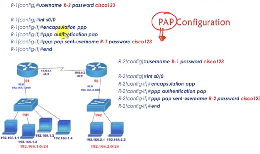
8.5 WAN Connectivity: PPP authentication
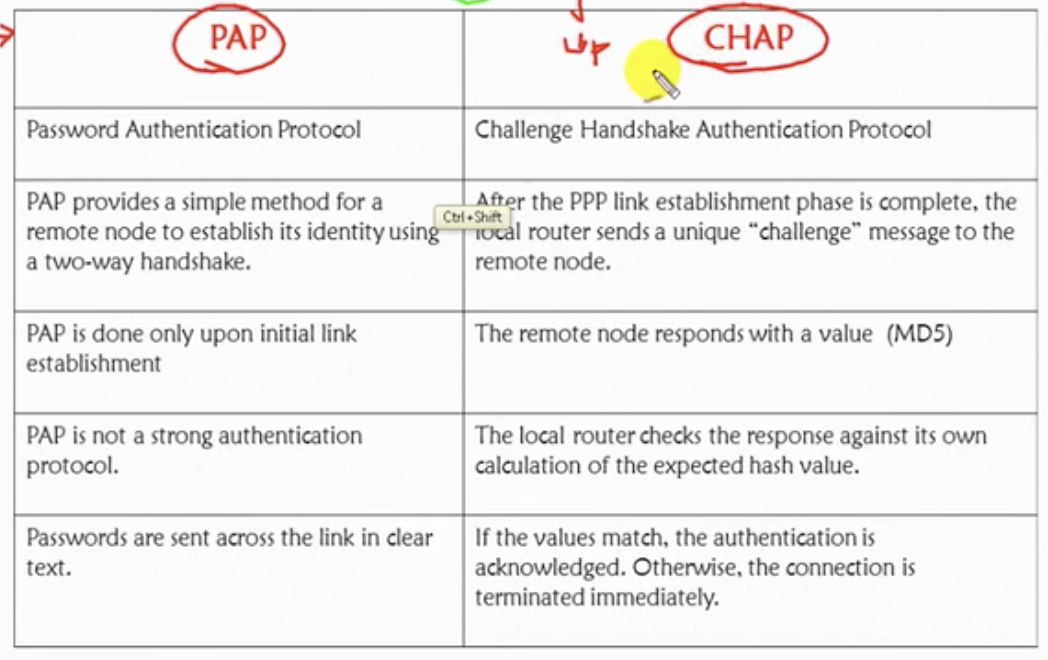
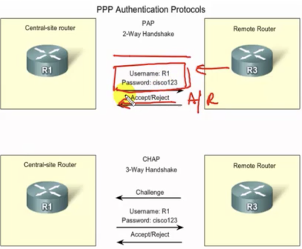
Two different types of authentication: PAP and CHAP.
|
|
PAP
- PAP is just a two-way handshake process. Whenever the link between two routers is established, one router is going to send the username and the password and the router on the other side will check the username and the password. If they match, they accept the request. Otherwise, it rejects.
- Major drawback is that the password is sent in a clear text, which obviously is not desired.
- The password and username are not sent at first. The other router sends a 'challenge' (hash value requesting for the username and password) and based on that, the router sends the username and password. If the hash values match between the routers, the other router is going to accept the request. So in actuality the routers are never sending the actual password, but the hash value.
Configure CHAP for routers: commands
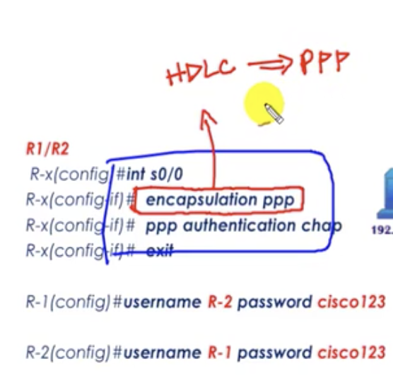
- If you only configure it on only one router, the protocol would be 'down' when you type show ip interface brief because of the encapsulation mismatch.
- The router to be connected to must be specified with the exact hostname (R-2 and R-1 respectively)
- When you type the username and password correctly on each router, the line protocol should be up after a short time.
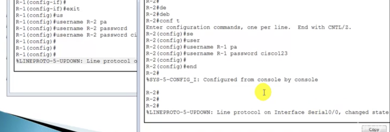
|
|
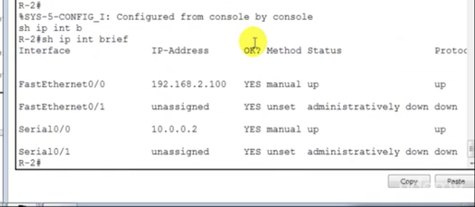
Notice that the protocol is now up for s0/0. Configuration successful.
show running-config will also verify that the configuration is successful.
show running-config will also verify that the configuration is successful.
Configure PAP for routers: commands
- The first four commands are exactly the same is CHAP.
- But there is one additional command to add because the username and the password are generated manually by the administrator.
Removing previous configuration (ex. PPP-CHAP) on certain interface (for example, s0/0)
Router(config)#interface s0/0
Router(config-if)#no ppp authentication chap
Router(config)#interface s0/0
Router(config-if)#no ppp authentication chap
Checking/troubleshooting the connection
1. show ip interface brief
2. ping [IP address]
1. show ip interface brief
2. ping [IP address]
9.1 Routing: Introduction
Remember from the previous chapter that we still need to configure routing to finalise te WAN connection.
Routing
Types of routing
1. Static routing (basic concept)
3. Dynamic routing (most commonly used)
Routing
- The process of forwarding packets from one network to another network.
- The router will choose the best path from the routing table.
Types of routing
1. Static routing (basic concept)
- Manual routing. Administrator has to decide the path. In case several routers are connected to each other, there may be more than two possible routes. The admin selects one of the routes.
3. Dynamic routing (most commonly used)
- Automatic routing done by routing protocols. The router chooses the best path.
9.2 Routing: Static routing
Basic characteristics
Router(config)# ip route <Destination network ID> <Destination subnet mask> <Next-hop IP address>
- Static routing is manually configured by the administrator (the path)
- Must know the network ID and the subnet-mask of the destination.
- Secure & fast because the router does not need to calculate the route (already decided by admin)
- Used or small organisations with a network of 10-15 routers. You need to tell every single router how to reach each router to reach the destination router. The bigger the number of routers, the bigger the number of the routers to be configured manually. Something not just possible on big networks.
- Administrative distance for static route is 0 and 1. It is the trustworthiness of the routing information. Lesser the administrative distance, higher the preference (covered in more detail in later chapters)
- used for small network only
- everything configured manually (if you want to go from A to D through A-B-C-D, you have to tell how to go from A to B and B-C and C-D.
- network changes affect the complete network. If the connection is set as A-B-C-D and there is a problem in B, the whole route from A-D will be down. In this case the admin has to manually recognise the circumstance and change the route. What if a new router comes in? It has to be written with the information about all the existing routers.
Router(config)# ip route <Destination network ID> <Destination subnet mask> <Next-hop IP address>
9.3 Routing: Static routing lab
Say, you've got two routers.
- R1 uses 10.0.0.1 and R2 10.0.0.2.
- You want to ensure the connection between the LANs.
- Use the same topology setup from the previous chapters as shown below. All specified interfaces should be up. Go onto each PC and type ipconfig and do ping [other IP addresses] to check the connection with other computers or the routers.
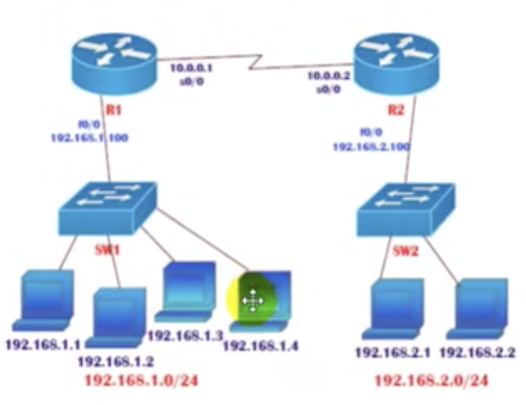
Now the problem you get when you try to reach another PC over WAN is that there is a reply from the local router (gateway) saying "destination host unreachable" as shown below.
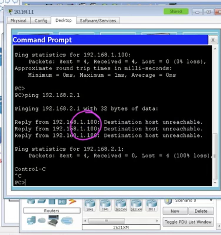
Then, do show ip route on the CLI of R1 to check its connections with R2 and the LAN (192.168.1.0/24) as shown below. But it does NOT know about 192.168.2.0/24 network. In the same way, R2 does NOT know about 192.168.1.0/24 network. We need to tell the routers about these networks.
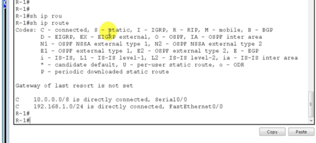
See the last two lines: it only knows about 10.0.0.0/8 and 192.168.1.0/24. So how to tell the router about the remote LAN?
Adding the static route manually on a router's CLI
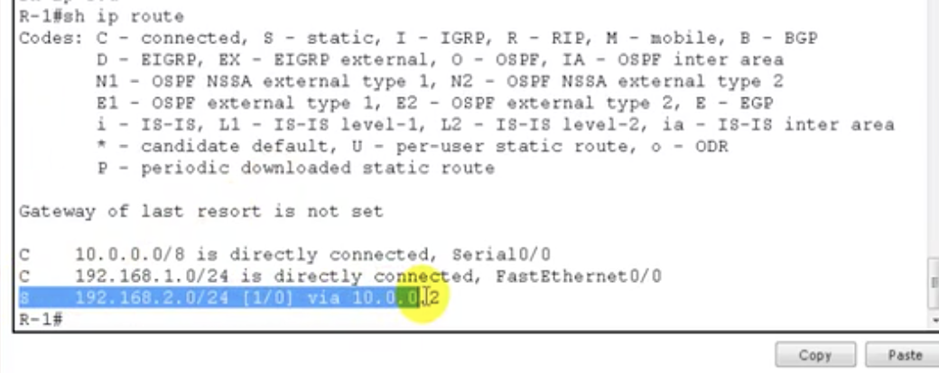
now R1 knows where the network 192.168.2.0/24 is and which router it has to go through to reach that network. But the problem now is that the packet can be sent, but there will be no reply, because R2 does not know about the network 192.168.1.0/24. The same kind of configuration is therefore needed for R2.
R2 currently knows about 192.168.2.0/24 and 10.0.0.0/8 without ny configurations by default. So we need to let it know about 192.168.1.0/24 as well.
R2 currently knows about 192.168.2.0/24 and 10.0.0.0/8 without ny configurations by default. So we need to let it know about 192.168.1.0/24 as well.
Adding a remote LAN on the other route
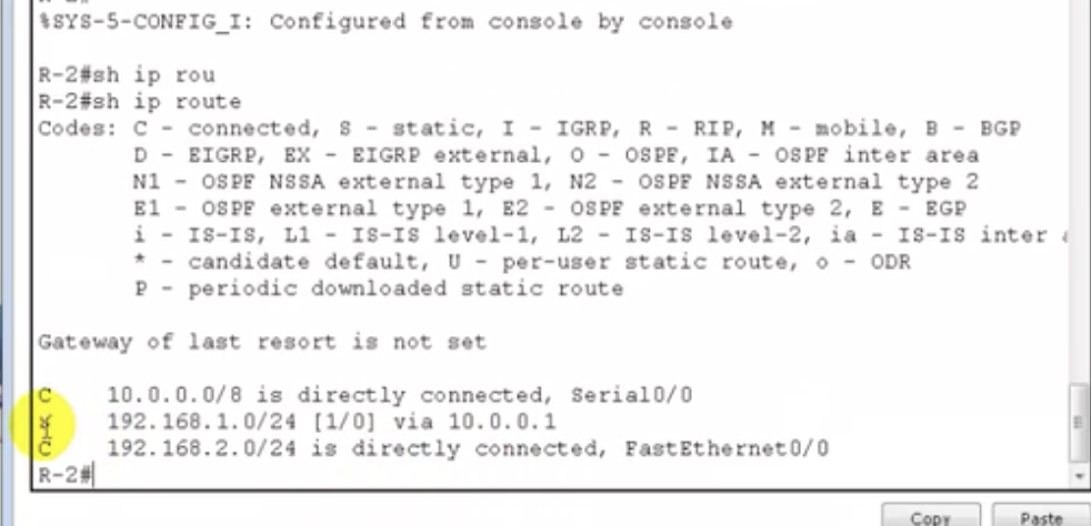
|
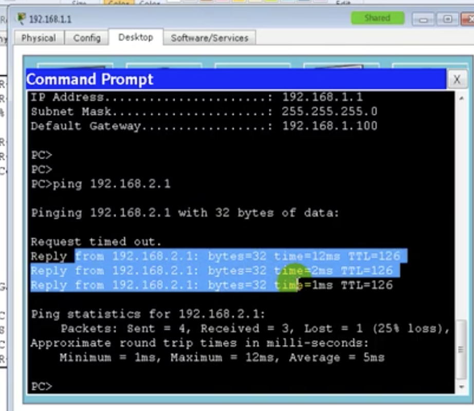
|
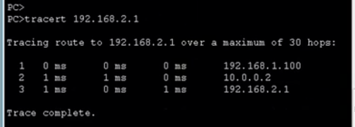
|
9.4 Routing: Static routing - 3 routers
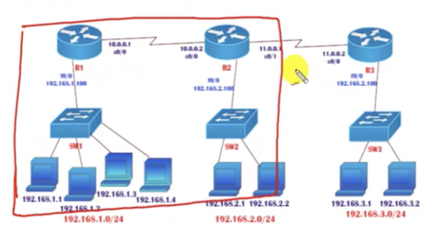
Now we have three routers to be configured as above. Some additional routing is required to enable individual PCs to communicate over WAN.
1. Figure out how many networks there are:
3. Configure connections to the networks to which the router is not directly connected.
But what if the user in R1's LAN wants to communicate with the user in R3's LAN?
ip route 192.167.3.0 255.255.255.0 10.0.0.2.
No additional configuration is needed, as R2 will take care of what's happening from there.
You want to let routers communicate as well:
ip route 11.0.0.0 255.0.0.0 10.0.0.2
4. Check the connections on the CLI using show ip route / ping / tracert.
But the more LANs you have, the more configurations you have to take care of.
1. Figure out how many networks there are:
- 192.168.1.0
- 192.168..2.0
- 192.168.3.0
- 10.0.0.0
- 11.0.0.0
3. Configure connections to the networks to which the router is not directly connected.
But what if the user in R1's LAN wants to communicate with the user in R3's LAN?
ip route 192.167.3.0 255.255.255.0 10.0.0.2.
No additional configuration is needed, as R2 will take care of what's happening from there.
You want to let routers communicate as well:
ip route 11.0.0.0 255.0.0.0 10.0.0.2
4. Check the connections on the CLI using show ip route / ping / tracert.
But the more LANs you have, the more configurations you have to take care of.
9.5 Routing: Routing lookup
How is the routing process actually happening? Understanding this is important in troubleshooting.
Whenever a computer is commanded to ping to a certain IP, it looks first at
1. if the IP address is on the same network.
2. If the destination is in a different subnet, the computer is simply going to forward the packet to the gateway (router). if the gateway is not defined, the computer never knows where the router is. It can only search inside the LAN in that case. So check the gateway always.
3. Once the packet has been forwarded to the router, the router is going to check the routing table. The router is not concerned about the exact IP address. It cares more about the network ID. If there is an entry in its routing table about the destination network (= argument input for ping) it will try to send the packet to there. Otherwise if an entry does not exist, it is going drop the packet.
4. The router will check again which interface it has to send the packet to. And finally the packet is sent via that interface to another router.
5. The same thing happens for the next router that received the packet from the previous router. If this router has the entry of the destination network, it is able to send the packet to there.
6. The router checks which interface it has to send the packet through. Then it sends the packet.
7. This process is repeated until the LAN where the destination network exists is reached.
8. When the router in the destination LAN is reached, again the same thing happens for fa interface and the packet is sent to the switch, which will run an ARP resolution to forward to the particiular host.
9.6 Routing: Default routing
Default routing protocol can be used for two cases:
Command example: R1(config)#ip roue 0.0.0.0 0.0.0.0 10.0.0.2
Case 1: Connecting to the Internet
When an end-user device needs to connect to the Internet-for example yahoo.com,
1. It converts the URL into an IP address and realises that the destination IP address and itself are on different networks. So it is going to forward the packet to the default gateway.
2. The router is going to check the routing table. It is going to see if there is an entry for that destination IP address. Of course it does not have the entry, so it will just drop the packet.
So you want to configure the network to direct the packet to the Internet, but not drop it. Then you must add the destination IP and the address of the router of on the way to the ISP to the routing table, which is simple. But the problem is that you have to do this for all the networks on the Internet that you want to access.
Solution: default routing. Configure a router, and tell it to direct the packets to the router that will pass the packet to the ISP when it cannot find the destination IP address in its routing table:
IP route 0.0.0.0 0.0.0.0 [IP address of the router of/to ISP]
the first 0.0.0.0 means any IP addresses and the second 0.0.0.0 means any subnet mask.
Default routing is mandatory when you want to connect a router to the Internet.
Case 2: End locations (where there is only one common next stop)
Say, you want to go from router E to B. The connection must include A, but from A, it could be either way: A-B or A-D-C-B. Same thing for other routers.
- when the destination is unknown (e.g. a destination on the Internet)
- when it's at end locations (optional)
Command example: R1(config)#ip roue 0.0.0.0 0.0.0.0 10.0.0.2
Case 1: Connecting to the Internet
When an end-user device needs to connect to the Internet-for example yahoo.com,
1. It converts the URL into an IP address and realises that the destination IP address and itself are on different networks. So it is going to forward the packet to the default gateway.
2. The router is going to check the routing table. It is going to see if there is an entry for that destination IP address. Of course it does not have the entry, so it will just drop the packet.
So you want to configure the network to direct the packet to the Internet, but not drop it. Then you must add the destination IP and the address of the router of on the way to the ISP to the routing table, which is simple. But the problem is that you have to do this for all the networks on the Internet that you want to access.
Solution: default routing. Configure a router, and tell it to direct the packets to the router that will pass the packet to the ISP when it cannot find the destination IP address in its routing table:
IP route 0.0.0.0 0.0.0.0 [IP address of the router of/to ISP]
the first 0.0.0.0 means any IP addresses and the second 0.0.0.0 means any subnet mask.
Default routing is mandatory when you want to connect a router to the Internet.
Case 2: End locations (where there is only one common next stop)
Say, you want to go from router E to B. The connection must include A, but from A, it could be either way: A-B or A-D-C-B. Same thing for other routers.
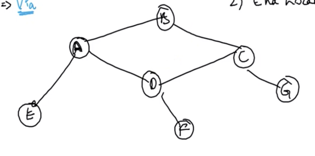
Notice that, to reach any destinations from router E, the traffic must. go through one common router, which is router A. What you could do is to configure multiple static routes from E to A,B,C,D,F... and so on respectively, or you could do ip route 0.0.0.0 0.0.0.0 [Ip address of A] so that router A takes care of everything. You can minimise static routing configurations. But on router A, you cannot use default IP routing because there are three possible paths.
9.7 Routing: Verify default routing
Applying default routing
In the WAN settings of previous chapter, you could use default routing on R1 or R3 because there is one common next-sop ( = the router is the end location). But still, for R2, which is in the middle, we have to use static routing because it is connected to three different networks.
Configuring default routing on a router (R1)
fire up CLI and type in ip route 0.0.0.0 0.0.0.0 [next stop IP address]
Notice that at the bottom line of the last output, the line with:
S* 0.0.0.0/0 [1/0] via 10.0.0.2
is added. This one is for the default routing.
check the connection with:
1. ping
2. tracert
S* 0.0.0.0/0 [1/0] via 10.0.0.2
is added. This one is for the default routing.
check the connection with:
1. ping
2. tracert
NAT is used in a real network scenario (don't have to be interested too much in this as of now)
In the connection from a router to an ISP, default routing is always used. But from ISP to the router, static routing is used for the public network. You are going to only use private IP for the LAN. And whenever you request some information from the Internet, your computer's IP will be given some public IP address using NAT. The ISP is going to define your network with your computer's public IP.
In the connection from a router to an ISP, default routing is always used. But from ISP to the router, static routing is used for the public network. You are going to only use private IP for the LAN. And whenever you request some information from the Internet, your computer's IP will be given some public IP address using NAT. The ISP is going to define your network with your computer's public IP.
10.1: Dynamic routing: introduction
Advantages of dynamic routing over static routing:
Assume we've got 5 different locations: A,B,C,D,E.
If you wanna go from A->E, you have two ways. If you are using static routing, the best route will be decided by the admin.
- Works with advertisements (of directly connected networks)
- No need to know the destination networks.
- Updates the topology changes dynamically
- Administrative work is reduced
- Can be used for large organisations (more scalable)
- Neighbour routers exchange routing information and build the routing table automatically.
Assume we've got 5 different locations: A,B,C,D,E.
If you wanna go from A->E, you have two ways. If you are using static routing, the best route will be decided by the admin.
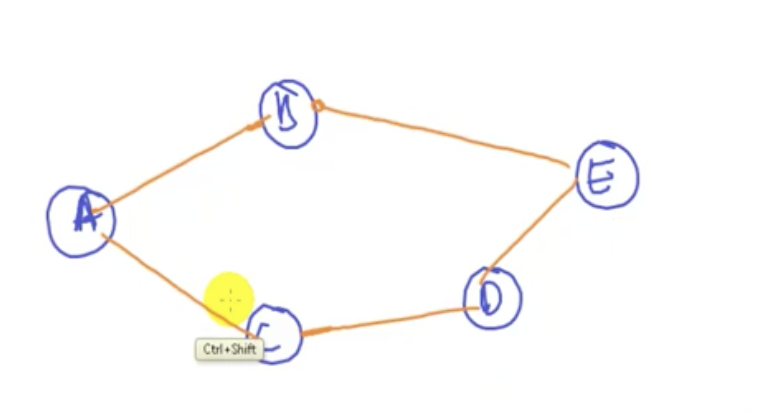
Router A does not need to know about the existence of other routers; it is going to learn it automatically from advertisements. Router A is going to advertise itself to router B. Router B knows about router B and A. Then router B sends information over to router E. router E now knows there are router B,A, and E. And the same thing happens for A-C-D-E. So eventually router E will know that there are two ways to reach router A, because the information will be transferred to E twice, through A-B-E and A-C-D-E.
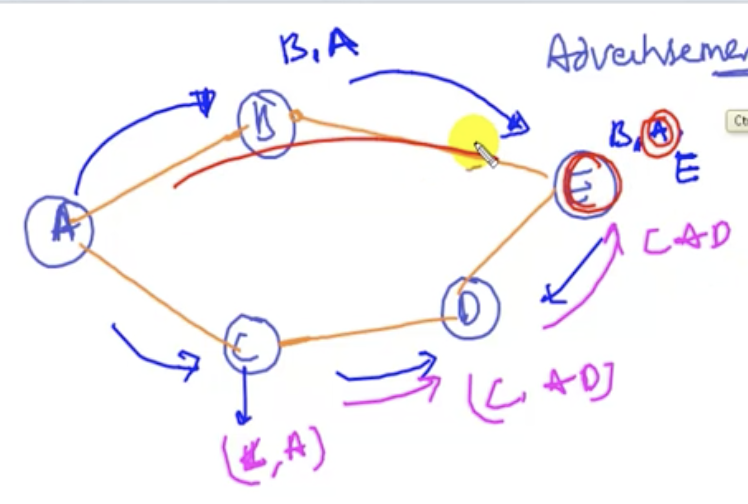
E is going to decide the best route on its own and communicate with A when it needs to. And in case the best route goes down, router E also knows about the alternative route, so it is going to forward its traffic to there. No need for manual setup.
10.2: Dynamic routing: protocols
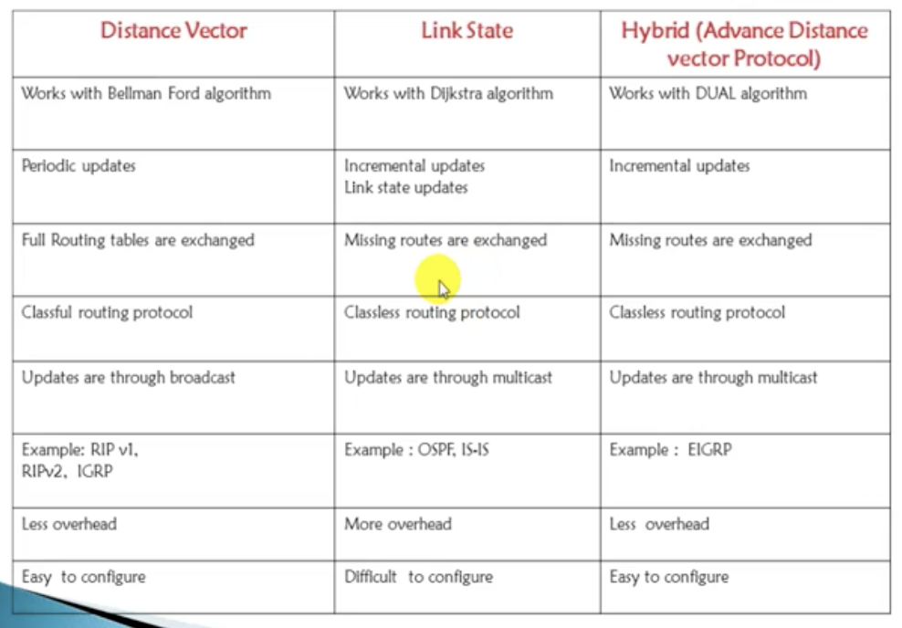
functionality-wise comparison
Distance vector
The first protocol introduced is the distance vector protocol.
In today's networks, the most commonly used protocols are OSPF and ElGRP.
Classful protocols
Classful routing protocol does not carry the subnet mask information along with updates.
Means all devices in the network must use the same subnet mask (FLSM or default) Ex. RIPv1, IGRP. For example router A is using 192.168.10.0/28 network (subnetting). And there are two routers. One of the routers is going to send a network information to another. But there will be no information about subnet mask. But there will be a problem if routers have different subnet masks of their own networks because they are going to emit wrong information.
Classless protocols
Classless routing protocol carries the subnet mask information along with updates. Means it supports sub networks (VLSM and FLSM) and default networks as well. Ex. RIPv2, EIGRP, OSPF, IS-IS. This allows the remote routers to understand the exact range of addresses that a router is using.
The first protocol introduced is the distance vector protocol.
- It does a period update. Say the interval is 30 secs, then a router using distance vector protocol will send info about itself every 30 secs to its adjacent routers.
- Router A knows about A,B,C,D,E. Then it is going to send the complete routing table when exchanging information with a time interval.
- Broadcast. If any update comes to one router, it simply sends that update to all the interfaces that it has.
- Incremental updates: whenever there is a change. Say, there is a new router installed, or there is a router removed. Then there is going to be an update. Compared with periodic update, it's much better. Distance vector is going to use more bandwidth.
- Say router F is added. Then router A, if it knows about this update, is only going to send info about router F. Say router B is down. Then router A is going to update other routers on that.
- Multicast. Able to identify the interfaces to which it has to send updates.
- Overall, these features are better than those in distance vector.
- But because of more processing caused to the CPU, there is going to be more overhead.
- ElGRP: upgraded version of IGRP
- It carries the best features of above protocols.
In today's networks, the most commonly used protocols are OSPF and ElGRP.
Classful protocols
Classful routing protocol does not carry the subnet mask information along with updates.
Means all devices in the network must use the same subnet mask (FLSM or default) Ex. RIPv1, IGRP. For example router A is using 192.168.10.0/28 network (subnetting). And there are two routers. One of the routers is going to send a network information to another. But there will be no information about subnet mask. But there will be a problem if routers have different subnet masks of their own networks because they are going to emit wrong information.
Classless protocols
Classless routing protocol carries the subnet mask information along with updates. Means it supports sub networks (VLSM and FLSM) and default networks as well. Ex. RIPv2, EIGRP, OSPF, IS-IS. This allows the remote routers to understand the exact range of addresses that a router is using.
10.3: Dynamic routing: RIPv2
TRouting information protocol (RIP)
RIP timers
by default, there are 4 timers in RIP:
1. Update timer: 30 secs. Time between consecutive updates.
Sent every 30 secs.
2. Invalid timer: 180 secs. Time a router waits to hear updates. The route is marked unreachable if there is no update during this interval.
This is triggered when there is a failure in connection. A router sends a packet waits for a reply for 30 secs. The update does not come back. It waits for 150 secs more. The router is going to mark the route as 'invalid' during this 150 secs., meaning temporarily not working.
3. Flush timer: 240 secs. Time before the invalid route is purged from the routing table.
So after the previous 30 + 150 = 180 secs, a router is going to wait for 60 secs more, and removes the information on that route. (total 240 secs)
4. Hold down timer: 180 secs. Stabilises routing information and helps prevent routing loops during periods when the topology is converging on new information. Every neighbouring router is going to send information about hop count to a desired destination. And once a router receives that info, it is going to wait for 180 secs to see if other neighbours send advertisements. And then it is going to select the best route. If information comes after 180 secs, it is simply going to ignore. Hold down timer happens in two scenarios: (1) When a path that a router was using fails (2) when a router is first installed
- Not used in modern days.
- Open standard protocol. Can run on any vendors.
- Classful routing protocol. No subnet mask information
- Updates are broadcasted via 255.255.255.255 (to all interfaces)
- Metric: Hop count. Metric is a method used to decide the best route. Say you've got router A,B,C,D,E. If you want to go from A to E, there are two possible routes: ABE and ACBE. Router A is going to see hop counts from itself to router E. ABE has a hop count of 2. ACBE has a hop count of 3. Whichever route that has the least hop count will be selected. But what if there are more than two possible routes that have the same least hop count? Load balancing. It means using both paths. It actually supports up to 4 paths.
- Max hop count: only up to 15. 16th hop is unreachable.
- Max routers : 16 (including my router)
- Used for small organizations (drawback)
- Exchanges the entire routing table for every 30 secs
- Administrative distance is 120.
RIP timers
by default, there are 4 timers in RIP:
1. Update timer: 30 secs. Time between consecutive updates.
Sent every 30 secs.
2. Invalid timer: 180 secs. Time a router waits to hear updates. The route is marked unreachable if there is no update during this interval.
This is triggered when there is a failure in connection. A router sends a packet waits for a reply for 30 secs. The update does not come back. It waits for 150 secs more. The router is going to mark the route as 'invalid' during this 150 secs., meaning temporarily not working.
3. Flush timer: 240 secs. Time before the invalid route is purged from the routing table.
So after the previous 30 + 150 = 180 secs, a router is going to wait for 60 secs more, and removes the information on that route. (total 240 secs)
4. Hold down timer: 180 secs. Stabilises routing information and helps prevent routing loops during periods when the topology is converging on new information. Every neighbouring router is going to send information about hop count to a desired destination. And once a router receives that info, it is going to wait for 180 secs to see if other neighbours send advertisements. And then it is going to select the best route. If information comes after 180 secs, it is simply going to ignore. Hold down timer happens in two scenarios: (1) When a path that a router was using fails (2) when a router is first installed
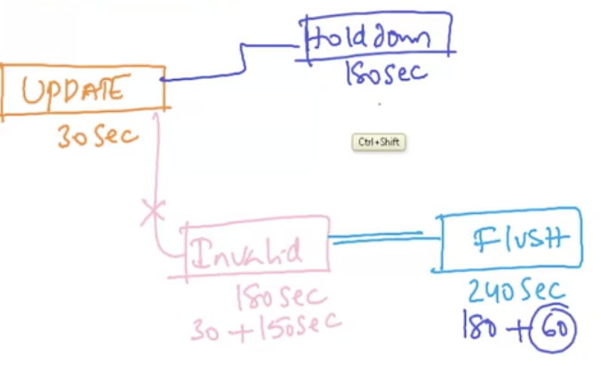
In sum, when a path that a router has been using fails, It is not going to emit any information before 240 secs elapse. This is the convergence time in RIP. It is very long compared to other protocols like EIGRP or OSPF.
RIPv2
Major enhancements in RIPv1 to RIPv2 include:
In today's networks, if we have to, we use RIPv2. No more RIPv1.
Major enhancements in RIPv1 to RIPv2 include:
- from Classful routing protocol to classless routing protocol
- from no authentication to authentication
- from broadcasts to multicast (multicast address = 224.0.0.9).
In today's networks, if we have to, we use RIPv2. No more RIPv1.
10.4: Dynamic routing: RIPv2 configuration
RIPv1 & RIPv2 configuration
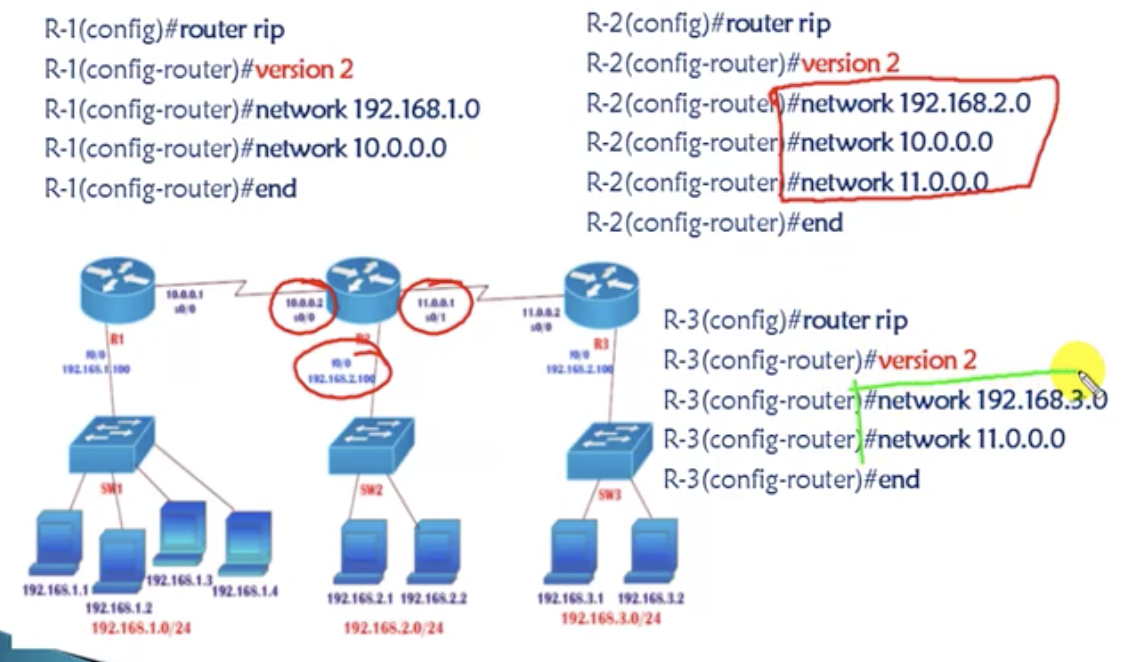
You want each LAN to be able to communicate with other LANs.
Actual output (R3)
Notice the numbers inside the square bracket at the bottom lines. For example:
R 10.0.0.0/8 [120/1] via 11.0.0.1, 00:00:09, Serial0/0/0
'120' in [120/1] represents administrative distance. And '1' represents hop count.
if you do 'show ip route rip', the CLI will only show the routing tables on RIP connections.
R 10.0.0.0/8 [120/1] via 11.0.0.1, 00:00:09, Serial0/0/0
'120' in [120/1] represents administrative distance. And '1' represents hop count.
if you do 'show ip route rip', the CLI will only show the routing tables on RIP connections.
show ip route rip & show ip protocols
for verification, same thing. Do:
1. ipconfig
2. ping
3. tracert
1. ipconfig
2. ping
3. tracert
Advantages of RIP
Disadvantages of RIP
- Easy to configure
- No design constraints like OSPF
- Less overhead
Disadvantages of RIP
- Bandwidth utilization is very high (update every 30 seconds)
- works only on hop count (does not consider bandwidth. Even if one route has a better bandwidth, if it does not have the least hop count, it would not be selected in RIP. It never considers BW.)
- not scalable because hop count is only 15.
- slow convergence, compared to other protocols (ElGRP: 15 secs. OSPF:40 secs)
10.5: Dynamic routing: Administrative distance
- It is the trustworthiness of the information received by the router. If a router learns about the same route from multiple sources, which source is it going to trust.
- The value is between 0 and 255.
- Less value means higher trustworthiness.
- Default administrative distances
- Directly connected = 0
- Static route = 1
- IGRP: 100
- EIGRP = 90
- OSPF = 110
- ISIS = 115
- RIP = 120
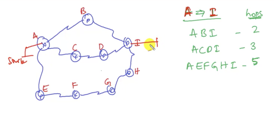
- Your router is A, and you wanna go to router I. There are three routes as specified above. RIPv2 decides the best route based on the hop count. So the route A-B-I will be chosen in RIPv2. (Administrative distance = 120)
- But an admin has also configured a static routing from A to I through A-C-D-I. (Administrative distance = 1)
- And for A-E-F-G-H-I, EIGRP is configured because it has the highest bandwidth. (Administrative distance = 90)
If the static routing fails, the router A will choose A-E-F-G-H-I that uses EIGRP, which has the next least AD.
10.6: Dynamic routing: Autonomous system number
- It is a unique number identifying the routing domain of the routers.
- An autonomous system is a collection of networks under a common administrative domain.
- Administrative domain ranges from 1 to 65535:
- public AS (in between multiple service provider): 1-64512
- private AS (same service provider): 64513-65535
You got companies A,B and C in three different locations. You wanna provide connectivity among these companies. You contact the service provider and then you can create WAN between your companies. Also you have another set of companies: X,Y,Z. They are also connected through WAN using the service provider. Now the question is: how is the service provider going to differentiate the traffic between the one for A,B,C and the one for X,Y,Z?
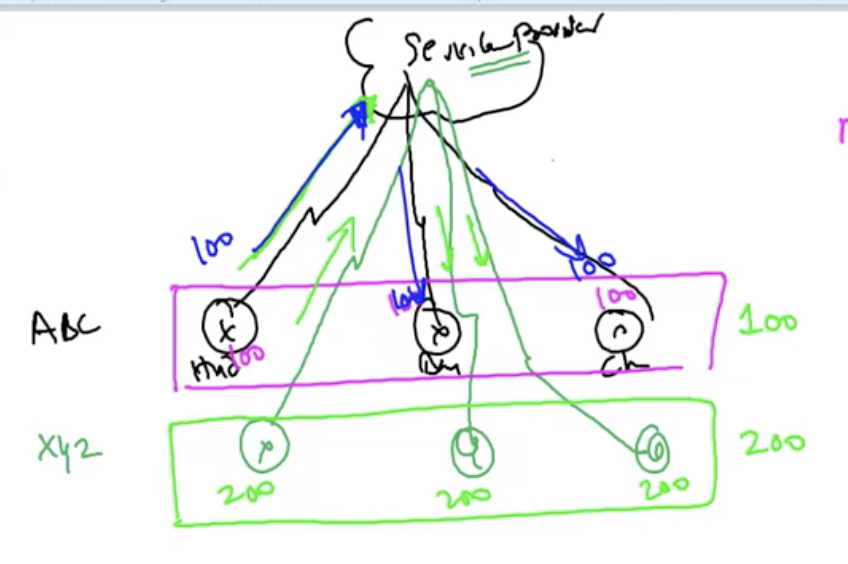
To differentiate, the service provider is going to assign an autonomous system number (AS number). Every WAN can be identified with an autonomous system number. So for example, if there is a traffic from WAN with the autonomous system number 100, the service provider will make sure that only the routers in that WAN with that autonomous system number receive the traffic.
And the companies X,Y,Z will be assigned a different AS number. So, simply it is a number that identifies a routing domain.
And the companies X,Y,Z will be assigned a different AS number. So, simply it is a number that identifies a routing domain.
Private AS vs Public AS
- Private AS number can be used inside the same service provider. This means the same AS number (ex. 65000) can exist across different service providers to identify different customers as shown in the diagram below. Similar to private IP address.
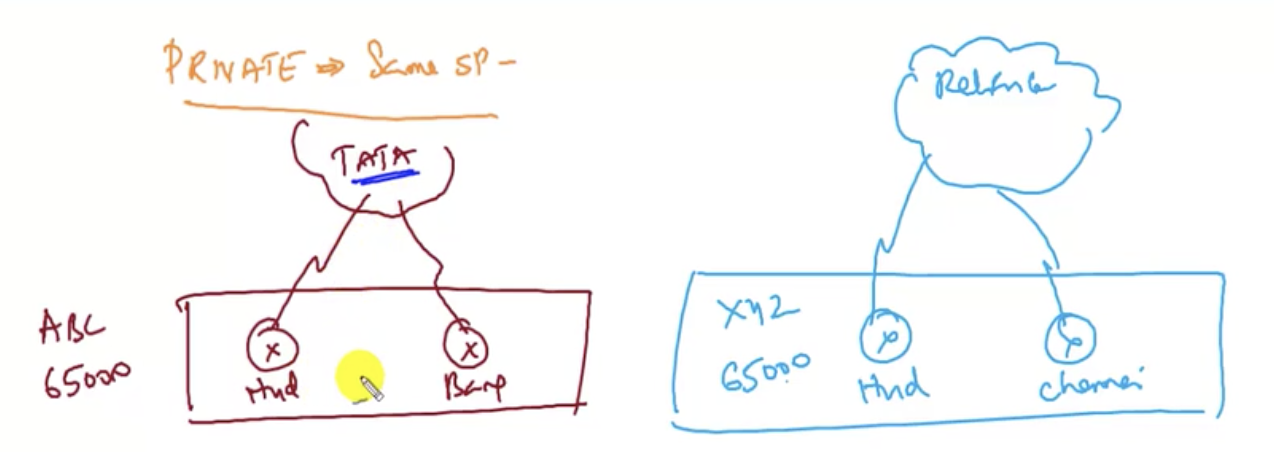
- Let's say the customer (ABC) is trying to send the traffic out to the Internet. Then the service provider will send its own AS. This is the service provider's AS. The private AS number is not recognised externally. The public AS number is used between multiple service providers. Public AS number is globally unique. When you are sending a traffic from one service provider to another, you us public AS.
Protocol categories: IGPs vs EGPs.
IGPs(Interior gateway protocols): operate within the same autonomous system.
EGPs(Exterior gateway protocols): only one kind of protocol. BGP (border gateway protocol). connect different autonomous systems. So ISPs connect with one another using BGP(a type of EGPs)
IGPs(Interior gateway protocols): operate within the same autonomous system.
EGPs(Exterior gateway protocols): only one kind of protocol. BGP (border gateway protocol). connect different autonomous systems. So ISPs connect with one another using BGP(a type of EGPs)
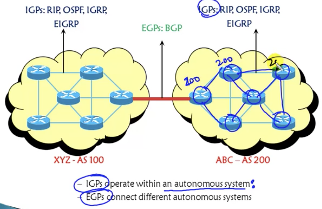
11.1: Dynamic routing-EIGRP: Introduction
Basic information
Process in EIGRP (below diagram)
1. Router A sends advertisement through multicast.
2. Router B replies with an advertisement through unicast.
3. They become neighbours of each other. They create a neighbour table.
4. Once they are neighbours, they exchange their own complete routing tables.
5. Upon retrieval of complete routing tables, they send acknowledgement to each other.
6. Then they have topology tables.
7. They then run an algorithm to calculate the best route.
To sum up:
1. Hello
2. Update
3. Routing table
- Enhanced Interior Gateway Routing Protocol.
- Advanced distance vector.
- Became a standard protocol (initially Cisco proprietary)
- Classless routing protocol (carries subnet mask information)
- Includes all features of IGRP (IGRP was modified to be EIGRP)
- Max hop count is 255 (100 by default. you can change it up to 255)
- Administrative distance is 90
- Flexible network design. You can design your network in any way in contrast to OSPF.
- Multicast and unicast instead of broadcast
- 100 % loop-free classless routing. No loops at all.
- Easy configuration for WANs and LANs.
Process in EIGRP (below diagram)
1. Router A sends advertisement through multicast.
2. Router B replies with an advertisement through unicast.
3. They become neighbours of each other. They create a neighbour table.
4. Once they are neighbours, they exchange their own complete routing tables.
5. Upon retrieval of complete routing tables, they send acknowledgement to each other.
6. Then they have topology tables.
7. They then run an algorithm to calculate the best route.
To sum up:
1. Hello
2. Update
3. Routing table
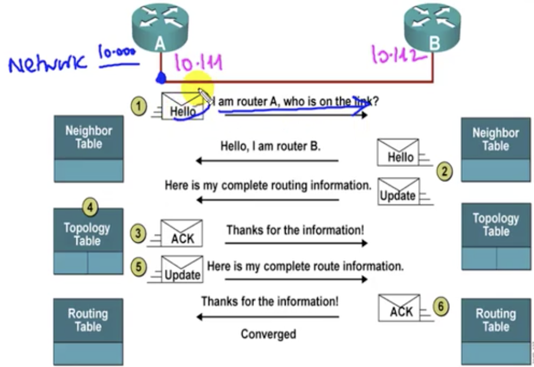
EIGRP tables
1. Neighbour table
Additional features
1. Neighbour table
- Contains list of directly connected routers only. Before doing anything, you have to have neighbors first. First thing you have to do before anything is this.
- Command: #show ip eigrp nighbor
- List of all the best routes learned from each neighbor. There may be several 'best' routes from one location to a certain destination. So it's like: each neighbour may have several routes to the destination that you want to go. But it only gives you only the best route. So you only get the routes for the topology table that equals the number of the neighbours that have a connection to the destination. (This is different from OSPF, where all possible routes are exchanged)
- Command: #show ip eigrp topology
- The best route to the destination. So it's actually the 'best route of the best routes'.
- Command: #show ip route
Additional features
- Updates are sent through multicast address 224.0.0,10
- The 'hello' packets are sent every 5 secs.
- Convergence rate is fast (only waits 15 secs)
- Supports IP, IPX, and Apple talk protocols
- It uses DUAL (diffusion update algorithm)
- Supports equal cost and unequal cost loading balancing. For example, if you have the same metric for two different 'best' routes, you will have an equal cost loading balancing. Otherwise you could do unequal cost loading balancing. This is a unique feature in EIGRP.
11.2: Dynamic routing-EIGRP: Metric
Basics
EIGRP uses BW, Delay, Load, MTU and Reliability to calculate a metric.
1. Bandwidth
Check values for bandwidth
if you want to check out these values on a router's CLI, do: show interfaces s0/0 and see the first few lines.
By default, the bandwidth is:
EIGRP uses BW, Delay, Load, MTU and Reliability to calculate a metric.
1. Bandwidth
Check values for bandwidth
if you want to check out these values on a router's CLI, do: show interfaces s0/0 and see the first few lines.
By default, the bandwidth is:
- 1544 Kbps for serial connection
- 512 Kbps for connection given by a service provider.
Code Editor
Change bandwidth
now there is a problem. EIGRP only recognizes the bandwidth on the interface, not the bandwidth of the connection given by a service provider. In order for it to get the effective bandwidth, you need to manually change the bandwidth, like this:
now there is a problem. EIGRP only recognizes the bandwidth on the interface, not the bandwidth of the connection given by a service provider. In order for it to get the effective bandwidth, you need to manually change the bandwidth, like this:
2. Delay
calculated in microseconds. The higher the bandwidth, the lower the delay.
calculated in microseconds. The higher the bandwidth, the lower the delay.
- Default serial link delay: 20,000 microseconds.
- Default ethernet link delay: 200 microseconds
- Default fastEthernet link delay: 100 microseconds
- Default 1-d link delay: 1 microseconds
Changing delay in case of anything
3. Load
ranges from 1 to 255. 1 is minimum and 255 is maximum.
4. MTU
Maximum transmission unit. When a traffic is sent, it is divided into several packets and each packet will be at maximum 1500 bytes, if MTU is 1500 bytes by default.
5. Reliability
calculated based on # packets being dropped or interfaces going up and down or sth like that. Ranges from 1 to 255. 1 is minimum.
Default K values.
Formula
- BW = K1 = 1
- Delay = K3 = 1
- Load = K2 = 0
- MTU = K4 = 0
- Reliability = K5= 0
Formula
- Metric = ( K1 * BW + ((K2*BW) / (256-load)) + K3 * Delay )
- But after sorting it out: Metric = K1 * BW + K3 * Delay. This is calculated automatically by routers and EIGRP protocol. They get something called 'cost'. Least cost is the best option.
EIGRP Metrics calculation example
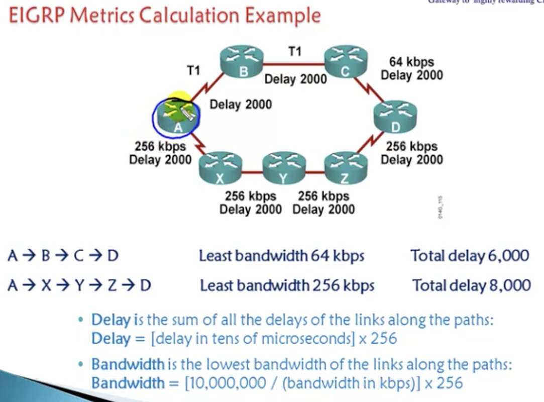
You wanna reach D from A.
- Calculating bandwidths: you are not going to average them or sth. You are going to take the least bandwidth in a route.
- Calculating delay: you want total delay. Just add them up along the route.
11.3: Dynamic routing-EIGRP: Configuration
Configuration command:
1. Router(config)#router eigrp <Autonomous system number>
The number could range from 1 to 65535. It could be any number. But this number must be the same for routers that want to form a neighborship with each other. Otherwise they cannot.
2. Router(config-router)# network <network ID of the target a router has to advertise to>
Then, just advertise. Depending the number of direct connections, this command could be given multiple times.
3. Verify using:
R2(config)#
- show ip eigrp neighbor
- show ip route
- show ip eigrp topology
- show ip protocols
- ping <another computer's IP>
- traceroute <another computer's IP>
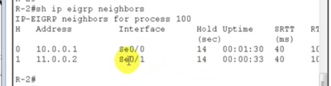
show ip eigrp neighbor
|
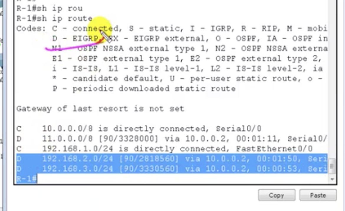
show ip route: [90/Something] means [AD/cost].
|
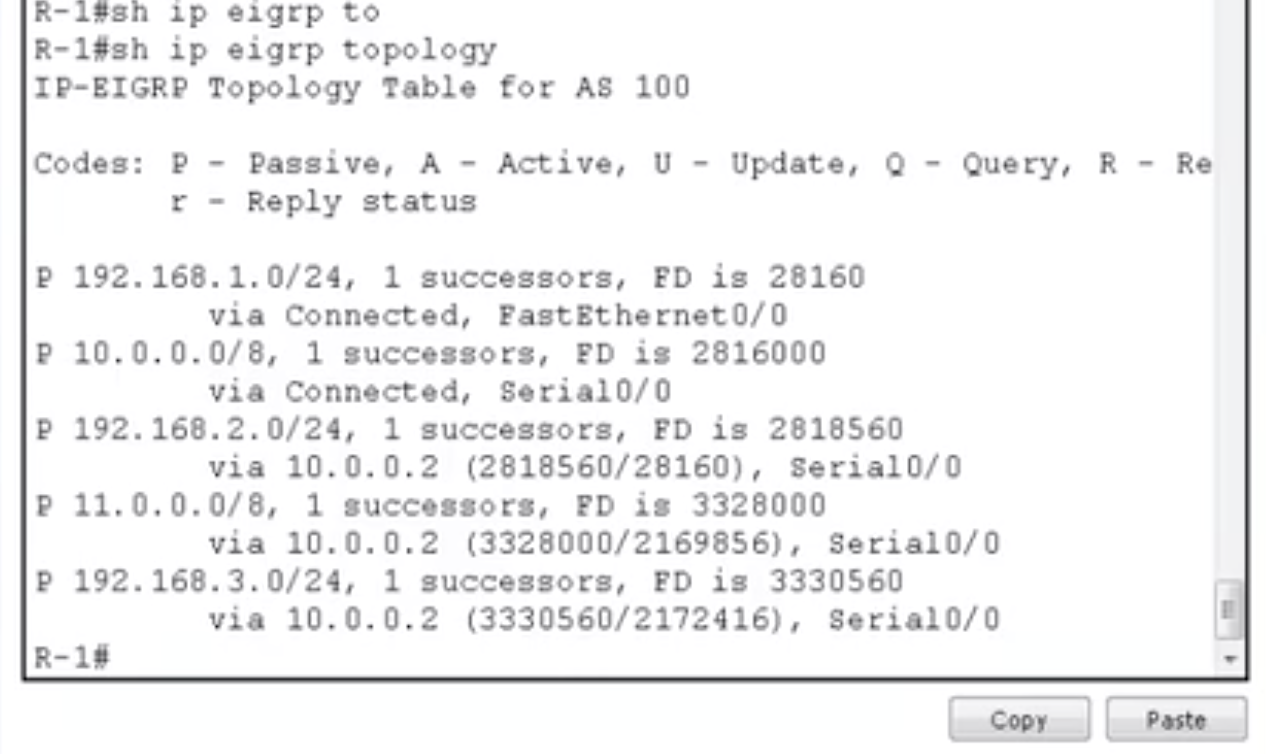
show ip eigrp topology
|
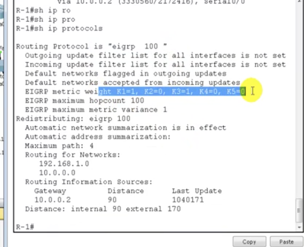
show ip protocols
|
Easy, less overhead, more scalable.
11.4: Dynamic routing-EIGRP: Feasible distance - advertising distance
Feasible distance
- Feasible distance is the total cost from local router to destination. You've got multiple routers in line and individual costs as specified in the diagram below (10, 20, 10...). If you wanna go from router A to a certain destination that is beyond router F, the total cost is just the incremental sum. So it's 110.
- Advertised distance = the cost between the next-hop router and the destination. So if your router is A and the destination is F, AD is 100.
- cost from local router = AD of next-hop router + cost between the local router and the next-hop router
- show ip eigrp topology
- [Feasible distance / Advertised distance]
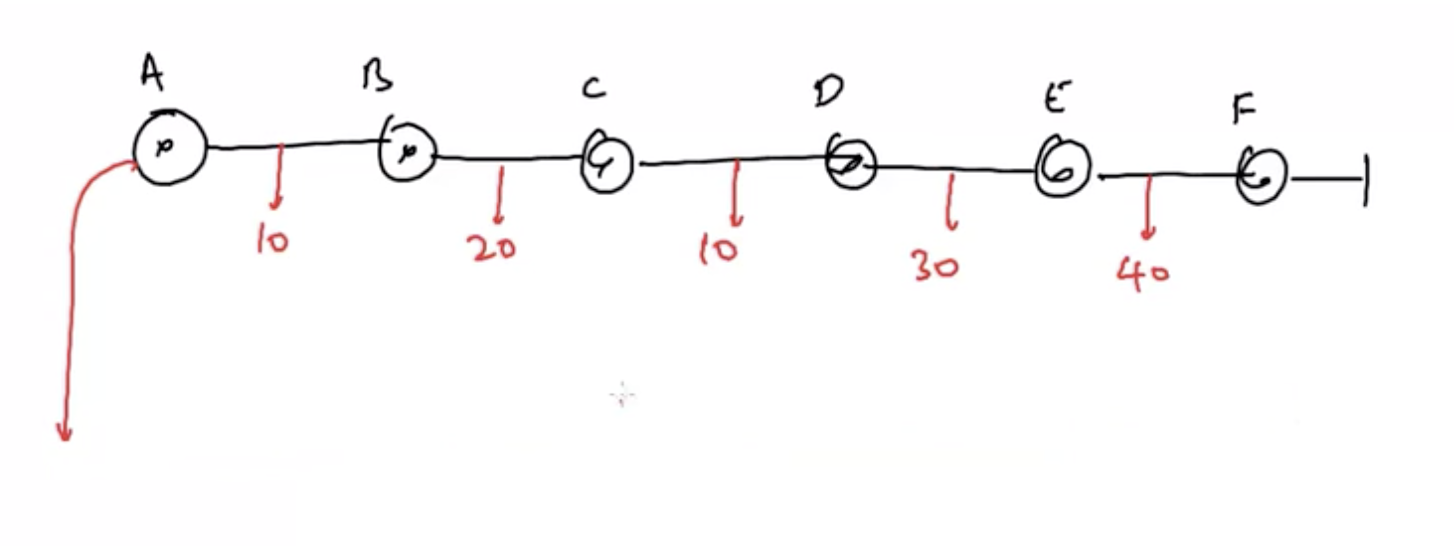
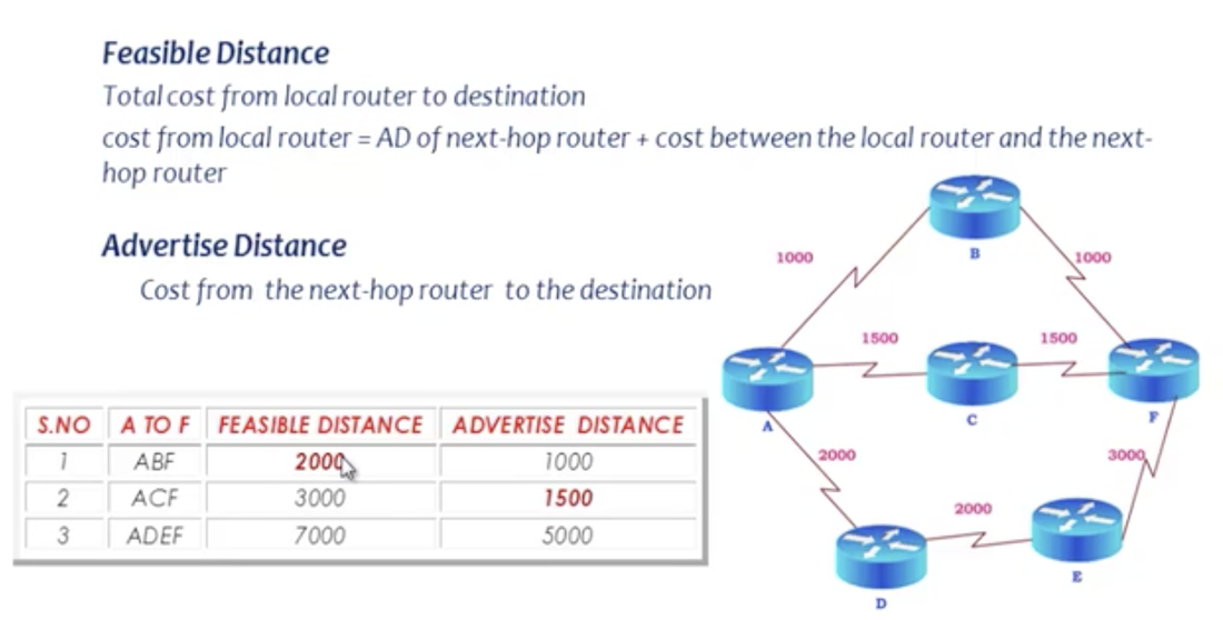
These concepts are important for feasibility conditions.
11.5: Dynamic routing-EIGRP: Feasibility condition
EIGRP pre-calculates the second best route if it satisfies the feasibility condition. Feasibility condition is where feasible distance of current successor route > advertised distance of feasible successor. Look at the table above in the previous chapter. The least cost is preferred, so the route ABF will be selected as the best route (successor). The second best route is ACF - the feasible successor. Look at the numbers in red, which are used to fulfil the feasibility condition.
- Successor is the best route to the destination. It is in the routing table and the topology table.
- Feasible successor is the backup path. It is in the topology table. In case the successor fails, this option is chosen.
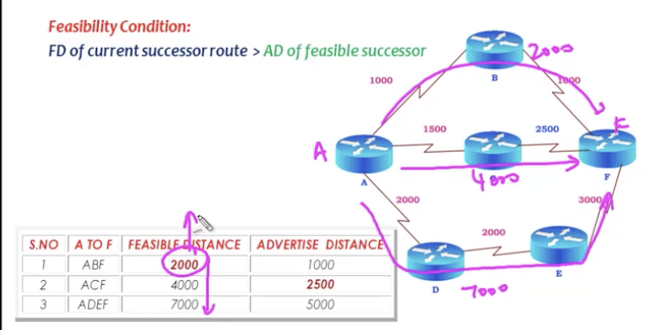
The feasibility condition is not satisfied here. Therefore, there is no feasible successor in this example. The condition ensures that feasible successor is trustworthy.
First scenario simulation
Second scenario simulation
- Get back to the first scenario (last chapter's last diagram). If the best route goes down, you have the feasible successor.
- In case the best route goes down, without calculation, the feasible successor will be chosen. And feasible successor is promoted to the routing table.
Second scenario simulation
- The best route fails. But there is no feasible successor. So if the best route fails, the router says it's got an alternative route, but it is not going to trust that information.
- So the router will only send query messages to directly connected routers.
- When it receives a reply from each route, it is going to update the feasible distances and advertise distances of the 'new' routes (the table above).
- Now the new bets route will be calculated and put into a routing table.
12.1: Dynamic routing - OSPF: seven stages in OSPF
Basic features
Basic process: 7 stages.
1. Down state
- Open shortest path first.
- Standard protocol.
- Link state protocol
- Uses SPF (shortest path first) or dijkistra algorithm
- Unlimited hop count
- Metric is cost (cost = 10 ^ 8 / Bandwidth)
- Administrative distance is 110
- It is a classless routing protocol (there is subnet mask information)
- supports VLSM and CIDR
- only supports equal cost load balancing
- Uses the concept of Area to ease management and control of traffics.
Basic process: 7 stages.
1. Down state
- Router A has an IP address of 172.16.5.1/24
- Router B has an IP address of 172.16.5.2/24
- They don't know about each other
- One router sends network information
- Multicast address 244.0.0.5 is used for communication. All OSPF-subject routers listen to this address.
- The other router receives the network information and replies with network information..
- The reply is sent as unicast.
- Neighborship is established. Neighbour table is made.
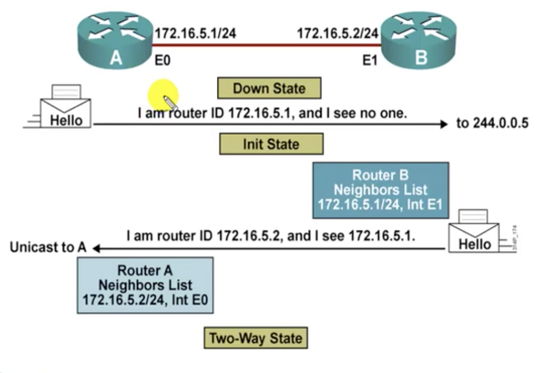
State 1-3
4. Exstart state
Router ID
Router ID
- Router ID is the highest IP address of the active physical interfaces of the router. Simply thought, it is the name of a router. In the example below,202.15.32.2/24 is the router ID.
- If a logical interface is configured, the highest IP address of the logical interface is Router ID. Loopback interface is just a logical interface used for testing purposes.
- So the preference rule for IP router ID goes like this: (1) it is the manually configured router ID. (2) if there is no manually configured router ID, it is going choose the logical interface (in this case, the loopback address) (3) If there is logical interface, the router ID will be the highest IP address of the active physical interface.
- Router ID has to be unique. It is only going to identify one router.
- Which router to send out information first is decided.
- The router with higher router ID will be selected to send information first.
- Routers decide to exchange information, but they don't at this state.
- DBD: Database description
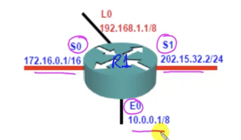
In case of OSPF, routers are allowed to use only one name (ID) each, instead of being identified multiple IP addresses like above.
|
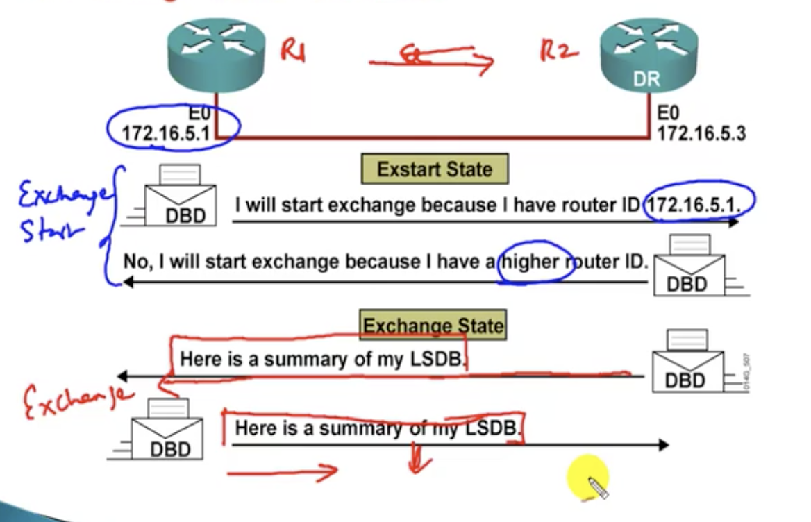
|
5. Exchange state
[ Before getting into step 6 ]
OSPF Tables
1. Neighbor table
- Actual transmission happens.
- The router that has higher router ID sends information first.
- LSDB: Link-state database
[ Before getting into step 6 ]
OSPF Tables
1. Neighbor table
- Also known as adjacency database
- Contains list of directly connected routers (neighbors)
- #show ip ospf neighbor
- Typically referred to as LSDB (link state databse)
- Contains information about all the possible routes to the networks within the area. Say, router A is connected to route B,C,D and router B knows 5 routes, C 3 routes and D 2 routes to a desired destination. And router A is going to know all possible routes (10 routes), which is different from EIGRP (distance vector protocol) where only the best route from each neighbour is received.
- This also means all the routers must have the same database in OSPF.
- # show ip ospf database
- Contains list of best paths to each destination
- # show ip route
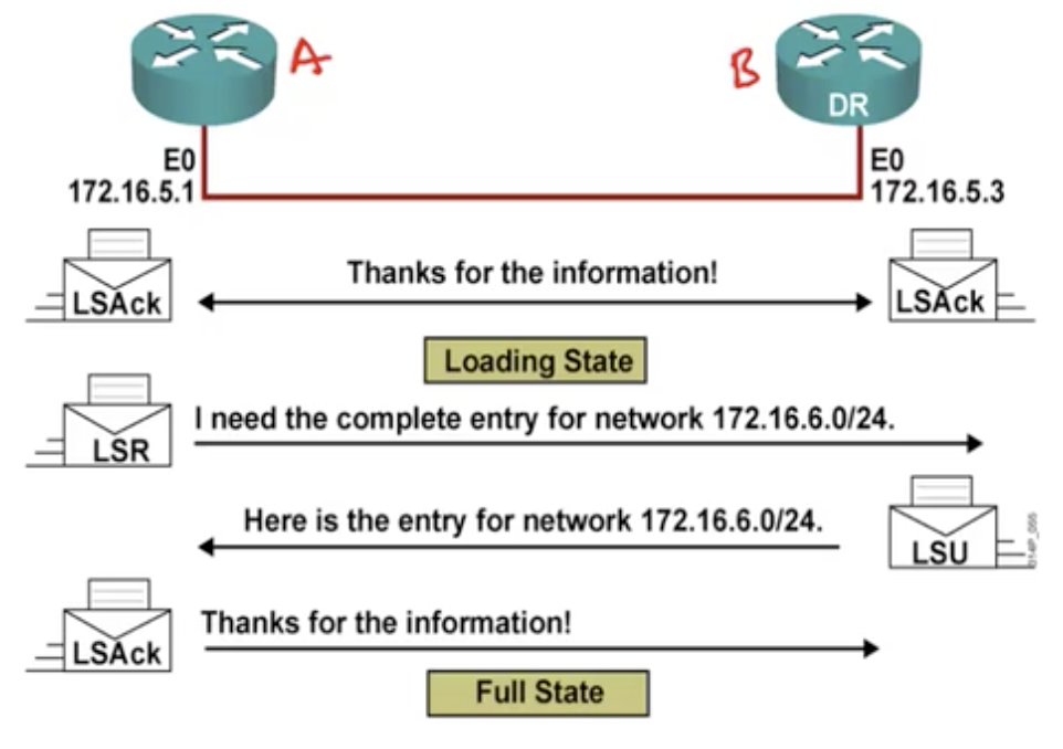
6. Loading state
7. Full state
- Router A checks its own database received from other neighbors against its own database made from the previous state.
- Router B and Router A make sure that they have the synchronized information between them.
- LSR: Link state request
- LSU: Link state update
- LSAck: Link state acknowledgement
- If there is any discrepancy between the two database tables, it is going to send a request for full entries and receive them.
7. Full state
- Both routers now have the same, synced database table.
12.2: Dynamic routing - OSPF: OSPF areas
Basics: why do we need areas
- All the routers maintain the same database. Then a problem arises in a big network: (1) the bigger the network, the harder it will be for access level routers to maintain the same database because of their limited memory capabilities. If such situation takes place, the memory-short router will normally reboot or something like that, which we don't want (See diagram below). (2) Distribution level routers will receive too many LSAs, because every single time there is a change in the network, an update will go around over all routers in the network. They will simply receive too much of advertisements. (3) The core layer router might be running too many algorithms in a big network. These are some general problems OSPF faces when it comes to a big network.
- Any changes impact all routers.
- Area is logical grouping of routers.
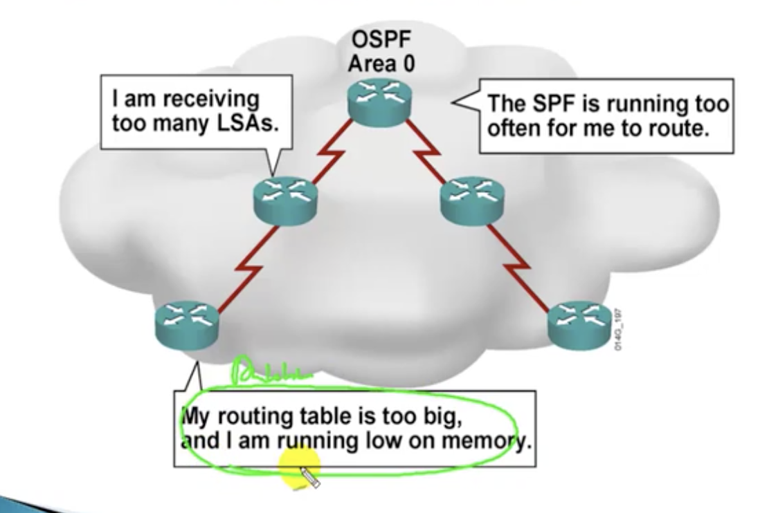
How area works
The solution to above problem is 'areas'. This means you are going to group the routers into big chunks of groups. Areas solve each problem posed above in this way:
(1) Areas will be given specific numbers to be uniquely identified. Now, the routers in the same area will only maintain information about their own area, but not other areas. So problem (1) solved.
(2) Any changes happening within the area will cause all the routers to participate in algorithm calculations, and will not affect other areas at all. Routers in other areas will not receive advertisements whenever there is a change.
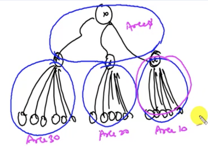
|
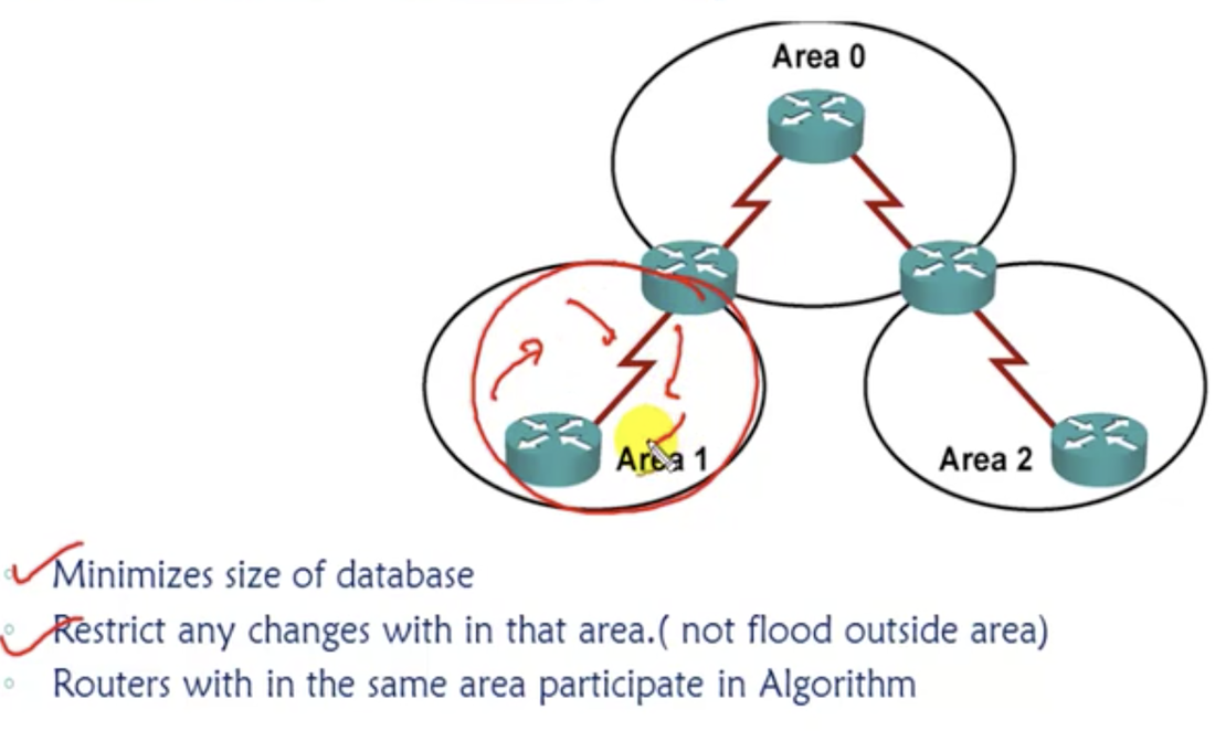
|
Conditions to follow
1. Cisco recommends not using more than 40-50 routers in one area.
2. Area 0 must be the centre (backbone area where the router at the top is included). Other areas are referred to as non-backbone areas. They can be numbered however they can be except using number 0.
3. Non-backbone areas cannot directly communicate with each other.
4. There must be at least one area border router (ABR). This is the router that is at the border between two areas. It is responsible for (1) exchanging the routes from one area to another area, (2) participating in algorithms of both areas (3) and maintaining the database of both areas.
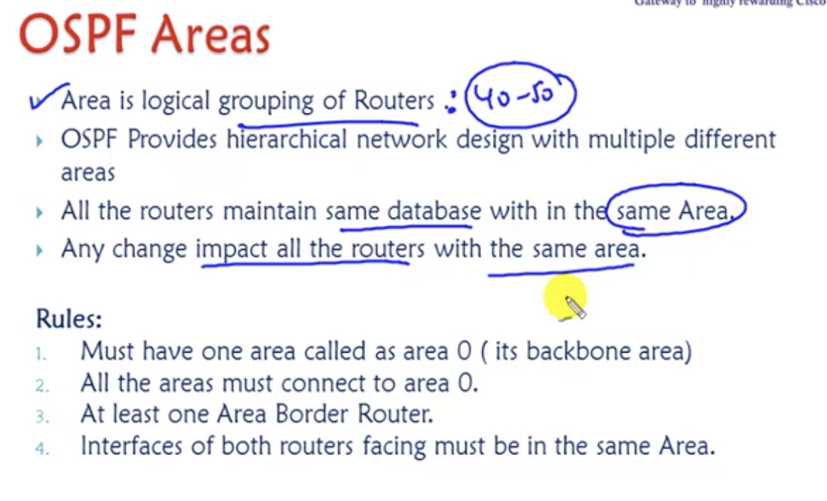
summary of the contents.
12.25: Dynamic routing - OSPF: Basic features of OSPF
Basic features
Basic features
- Updates are sent through multicast address 244.0.0.5
- Faster convergence: sends 'hello' packet every 10 seconds. No hello for 40 secs, mark the network as down.
- Incremental updates: updates sent only when there is a change.
- Open standard
- No hop count limitations
- Loop free
- Faster convergence (compared to RIPv2 )
- Consumes more CPU resources
- Complex design
- Supports only equal cost balancing (EIGRP supports unequal cost balancing as well)
12.3: Dynamic routing - OSPF: OSPF Single Area Configuration
1. (config)#router ospf <processs ID>
- define a process ID.
- process ID could be anything from 1 to 65535. It identifies an OSPF process running on a router.
- Say there are three different customers (routers) using OSPFs to connect to the service provider X. The SP wants to maintain separate OSPF process for each stream of OSPF so that the SP can run multiple OSPF instances without letting them interfere with each other.
- Process ID is locally significant: it could be the same or different across different routers. It does not matter.
- Note: it has nothing to do with AS numbers.
- advertise.
- wildcard mask: probably covered more in the later chapters. Simply subtract subnet mask from the global subnet mask (so if the network ID to advertise to is 192.168.1.0, do: 255.255.255.255 - 255.255.255.0 = 0.0.0.255). It's like an inverse mask. There are three zeros for first three network portions, so it is going to advertise to all the addresses of 192.168.1.*.
- So 0 means must match. 1 means ignore (the portion can be anything).
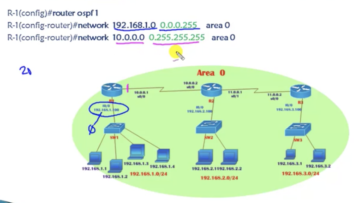
|
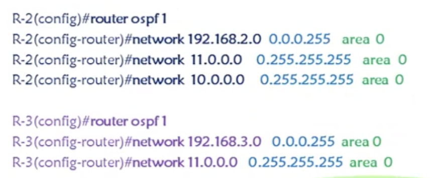
|
Single area configuration: hands-on
- It's pretty simple: just advertise to directly connected networks, and that will be it. The area number is 0. Remember how to calculate the wildcard mask.
- Verify using:
- show ip protocols (especially shows the router's own router ID)
- show ip ospf neighbor
- show ip route
- show ip ospf database
- ping [ip address]
- traceroute [ip address]
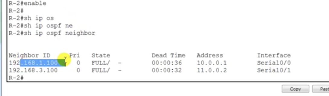
show ip ospf neighbor
|
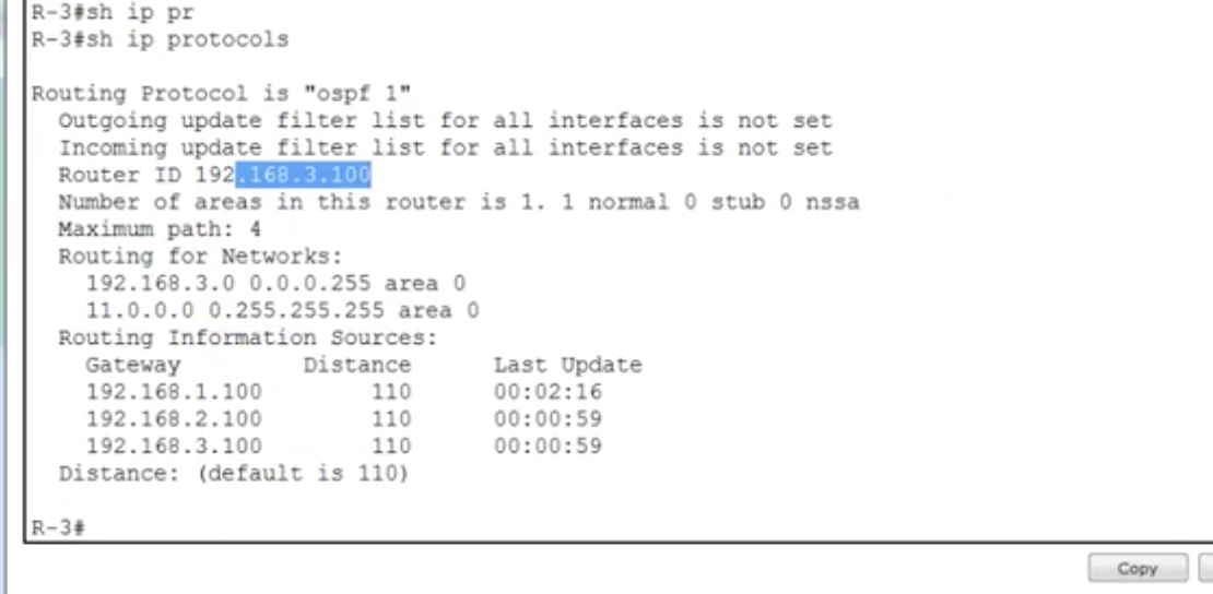
show ip protocols
|
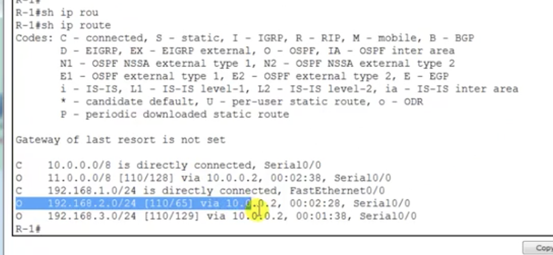
show ip route
|
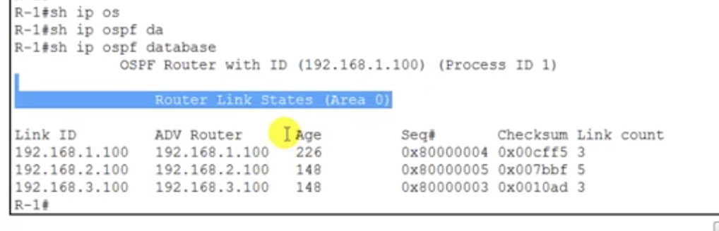
show ip ospf database
|
Notice that the neighbour ID is 192.168.1.100 and 192.168.3.100 (not 10.0.0.1 and 11.0.0.2) because neighbour ID is set as the highest IP address.
12.4: Dynamic routing - OSPF: OSPF multi-area configuration
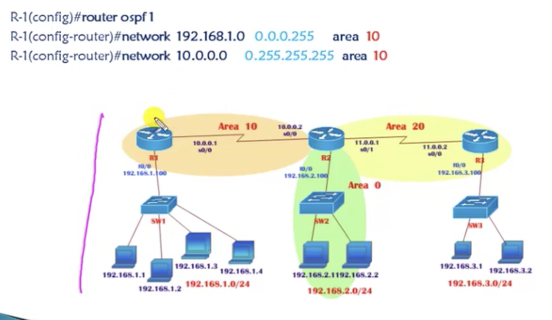
|
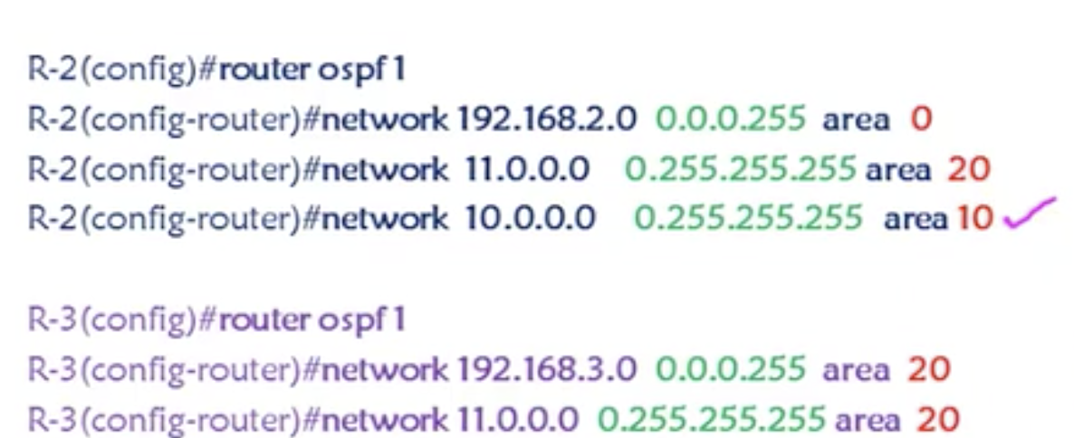
|
Notice that area 0 is at the center. R2 serves as an ABR. Configuration for R2 deals with all 3 different networks. You just need to configure the area number correctly. Difference arises for verification steps after you've completed configurations.
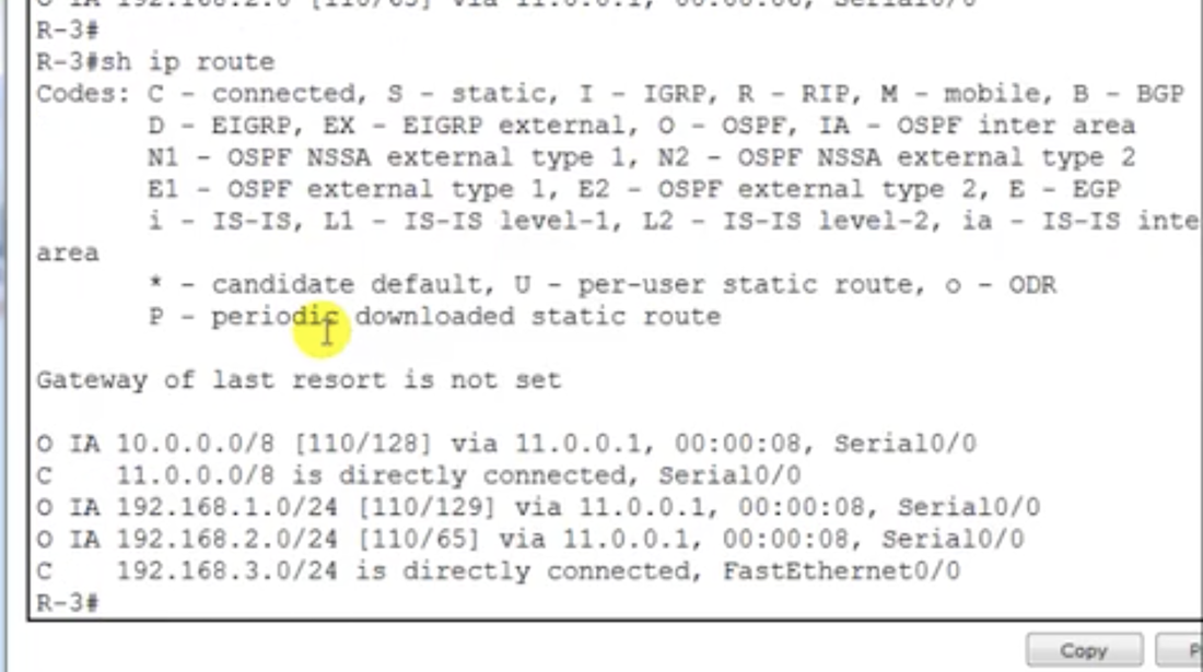
In the previous chapter, you saw 'O' routes, but you see 'O IA' here. This means a route coming from a different area. On R2, there are 'O' routes only, because it belongs to all of the areas.
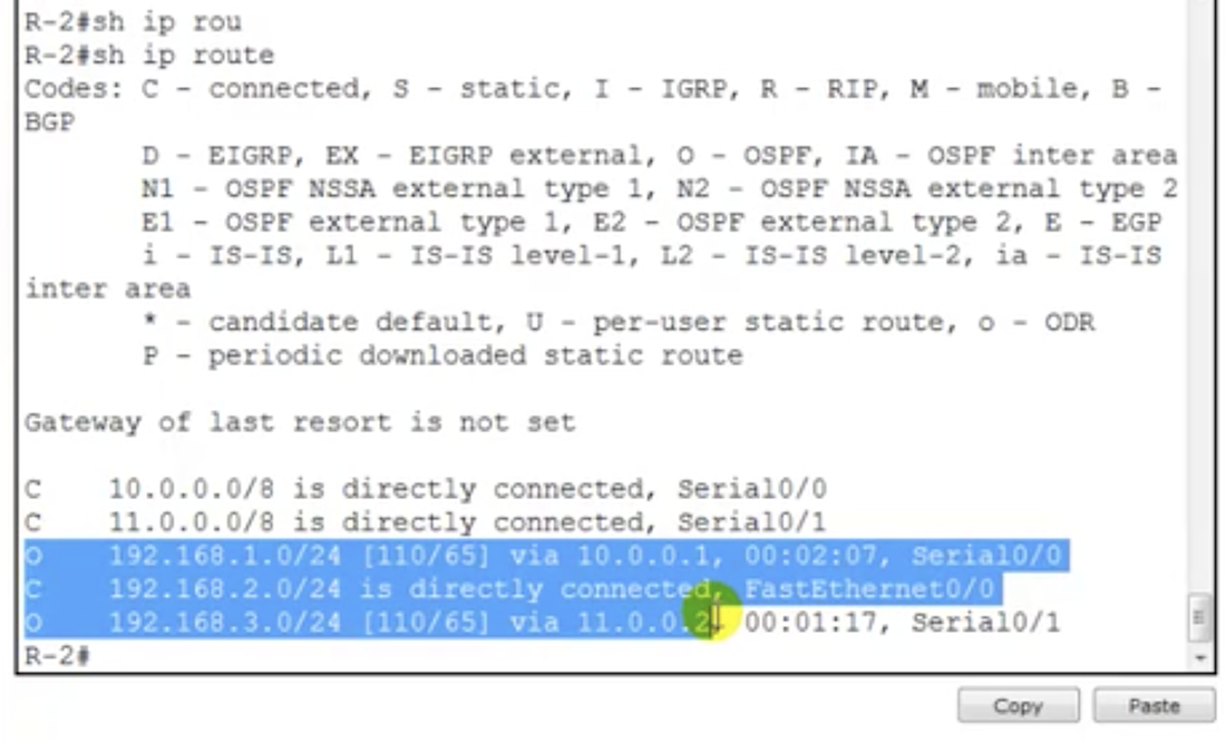
R2 will keep the database of all areas, and also participate in algorithm calculation of all areas. R1 and R3 will only keep the database of its own area only.
13.1: Basic switching: how switch learns MAC
A router provides WAN connections. Now, it's all about LANs. The switches.
Two devices used to provide LAN connections: hub and switch
Two devices used to provide LAN connections: hub and switch
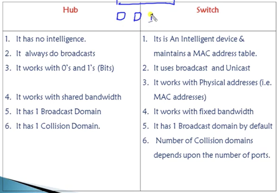
Switch
- Switch can identify devices with mac addresses by maintaining mac address table. Say, you've got a switch that has 6 ports and 6 devices connected to them. Devices are assigned 1.1 1.2 1.3 1.4 1.5 1.6 IP's. And devices have the following addresses: AA AB AC 2D 2E 3F.
- Now you want your device at 1.1 to communicate with device at 1.4. You ping the IP.
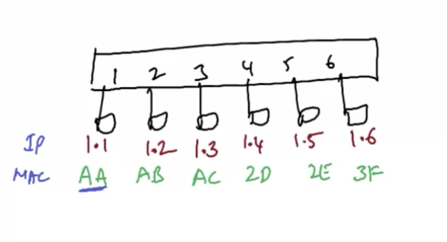
- But switches do not work with IP addresses. They only work with MAC addresses. Even though you ping an IP, a protocol called ARP (Address resolution protocol) to convert the IP address into a MAC address.
- The MAC address of 1.1 is AA, and of 1.4 is 2D. How does the switch find it out? Your computer at 1.1 is going to send a broadcast message (ARP request) to everyone asking what the MAC address at 1.4 is. Then the device at 1.4 is going to reply to that request with its MAC address.
- To verify, use ARP -a command. But ensure that you ping a device first. after that, ARP -a command will show the MAC address of the devices it has pinged.
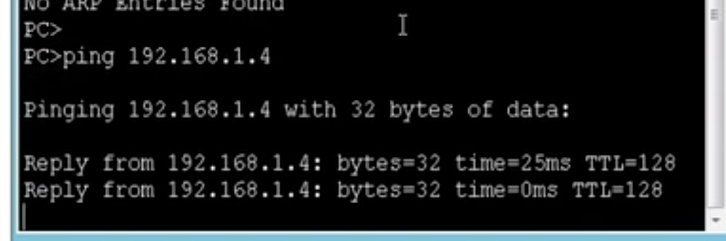
|
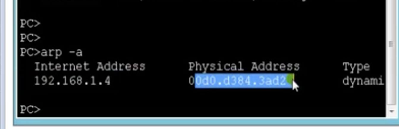
|
- Switches maintain a table called MAC table. In the table, there are port numbers and corresponding MAC addresses.
- If a device does not know about another device's MAC address, it is going to flood (broadcast). And the target device will reply to that via unicast. The entire process is again based on MAC addresses.
- On switch, broadcasting and replies happen continuously. And accordingly, the MAC table is filled out (when the switch is first turned on, the MAC table is empty).
- After knowing the MAC addresses of other devices, a device does not broadcast anymore unless it needs to access a new device.
- Default timeout timer is 300 secs. If there is no traffic from a MAC for 300 secs, the switch is going to remove the MAC address.
- Above is not applicable for hubs. Hubs are 'stupid'.
13.2: Basic switching: broadcast and collision domain
Broadcast domain & Collision domain
Broadcast domain
Broadcast domain
- Broadcast domain is the set of all devices that receive broadcast frames originating from any device within the set. You've got a switch and a device connected to it.
- And that device is going to broadcast itself to all other devices connected to that switch.
- The devices that receive the broadcast also include other switches connected to that switch because other switches are going to send the broadcast to other devices connected to other switches as well.
- A router is where the broadcast ends. It is not going to propagate the broadcast.
- Simply said, broadcast domain is all the devices in the LAN. If you have 500 devices in a LAN, then the remaining 499 devices will receive a broadcast from one device.
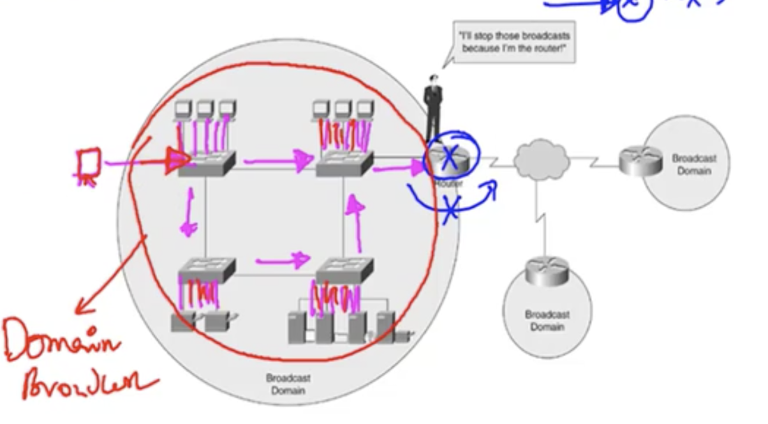
|
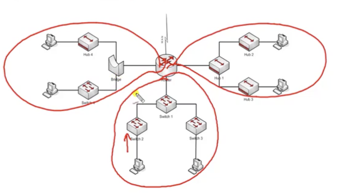
Total 3 LANs mean total 3 broadcast domain.
|
CSMA/CD and collision domain
- Carrier Sense Multiple Access / Collision Detection
- Collision domain is a network segment with two or more devices sharing the same bandwidth (where there is a chance of collision)
- protocol for carrier transmission access in Ethernet networks. Say there is a device connected to a LAN that wants to communicate with other devices in LAN. Just like when you cross the road, you see if there is a car beforehand, the device has to sense, to see any other devices are sending a data over the LAN. If something's going on already, you are probably going to stop. There is only one road (LAN) and only one device can do one thing at a time (just like a data bus in a computer) When any other device is not sending information over LAN anymore, the device starts to send off the data.
- But collisions still occur. When more than one device sense that there is nobody sending information over the LAN at the same time. Then there is a possibility of collision.
- In case of a hub, there is only one collision that domain (only one device in the hub network is allowed to send information. This is called shading of bandwidth)
- In case of switches, every port is like a separate network segment, and so every single port is a collision domain. Each port is assigned a dedicated bandwidth. Therefore there are no collisions taking place in a switch.
- Collisions are identified using access method called CSM/CD and CSMA/CA.
- CSMA/CD works in a wired LAN
- CSMA/CA works in a wireless LAN
13.3: Basic switching: basic configuration
Types of switches
Unmanageable switches
Initial configurations of a switch
Unmanageable switches
- 'plug-and-play' style
- No configurations and verifications have to be done
- No console port
- also 'plug-and-play' style
- Has console port and CLI access.
- Can verify and modify configurations and can implement and test some advanced switching technologies (VLAN, trunking, STP)
- Access Layer (Layer 2 Switches)
- Low performance
- Does a basic job of a switch
- Mostly used at end locations
- Distribution layer (Layer 3 Switches or multi-layer switches)
- Better processing
- Does a basic job of a switch
- Can do some routing jobs (exclusive in Layer 3 switches)
- Core layer (Layer 3 switches or multi-layer switches)
Initial configurations of a switch
- Use 9-pin cable to connect between the console port of a switch and console
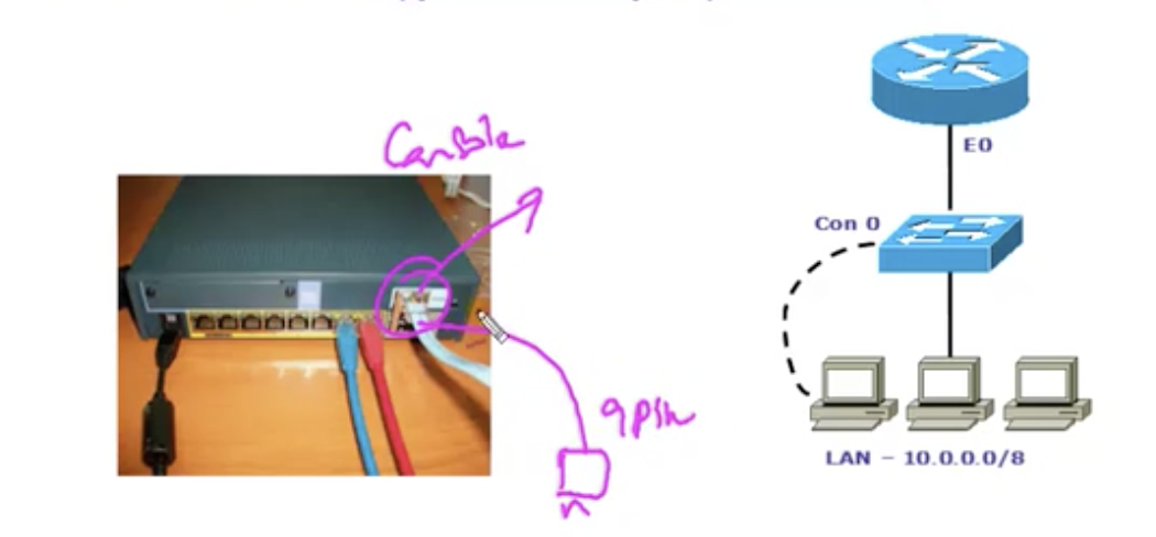
Basic commands (mostly covered in previous chapters)
1. Checking basics
New commands
1. Assigning an IP to a switch for management purpose (generally, in reality, switches would have IP addresses that belong to the same network as its LAN. The reason for that is telnet access. You wanna configure the switch via telnet. Then you need three conditions: (1) The switch and the device (usually PC) must be connected. (2) The device and the switch must have IP addresses. (3) vty password must be configured). FYI: Vlan is a virtual LAN. (4) enable password must be set
1. Checking basics
- show running-config
- show startup-config
- show version
- show flash
- show mac-address-table
- show interface status
- configure terminal
- line vty 0 4
- password <password>
- login
- configure terminal
- line con 0
- password <password>
- login
- configure terminal
- enable secret <password> OR
- enable passeword <password>
New commands
1. Assigning an IP to a switch for management purpose (generally, in reality, switches would have IP addresses that belong to the same network as its LAN. The reason for that is telnet access. You wanna configure the switch via telnet. Then you need three conditions: (1) The switch and the device (usually PC) must be connected. (2) The device and the switch must have IP addresses. (3) vty password must be configured). FYI: Vlan is a virtual LAN. (4) enable password must be set
- configure terminal
- interface vlan 1
- ip address <ip address> <subnet mask>
- no shutdown
- configure terminal
- ip default-gateway <default gateway address>
Configuration on a switch's CLI for telnet accessen
Confirming the connection from the PC & trying telnet connection
13.4: Basic switching: ARP resolution in WAN
Explained
You have a source address of 192.168.1.1 and the destination address is 192.168.3.1. This means you wanna transfer a packet from a local LAN to a remote LAN over WAN. How is it going to work? Assume that the MAC address of device at 192.168.1.1 is AB and that at 192.168.3.1 is 2C. And the routers as follows in the diagram. Packet transfer goes like this:
1. AB recognizes that the destination is in a different subnet, so it forwards the packet to the router (AC), not directly to the destination. The packet goes through the switch (SW1) as well. If there is a record of 2C in its mac address table, it is going to send as a unicast. Otherwise, broadcast.
2. The router AC will do routing. It will forward the packet to R2, and then to R3 (assume routing is done already).
3. Once the packet reaches R3, the MAC address of the source will change to 3D, because it's coming from the R3. Now the destination MAC address is finally 2C. The packet reaches the switch (S3) and determines if it is going to send unicast or broadcast to its connected PCs.
In sum, the IP address of the source and destination will not change. But the MAC addresses will change according to where the packet is in the course of transfer.
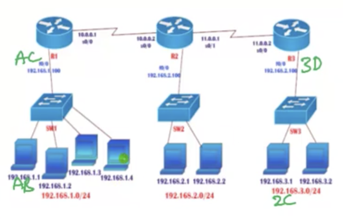
14.1: VLAN and Trunking: VLAN introduction
Basics
- VLAN is a virtual LAN. it divides a single broadcast domain into multiple broadcast domains. It is going to minimise the number of broadcasts.
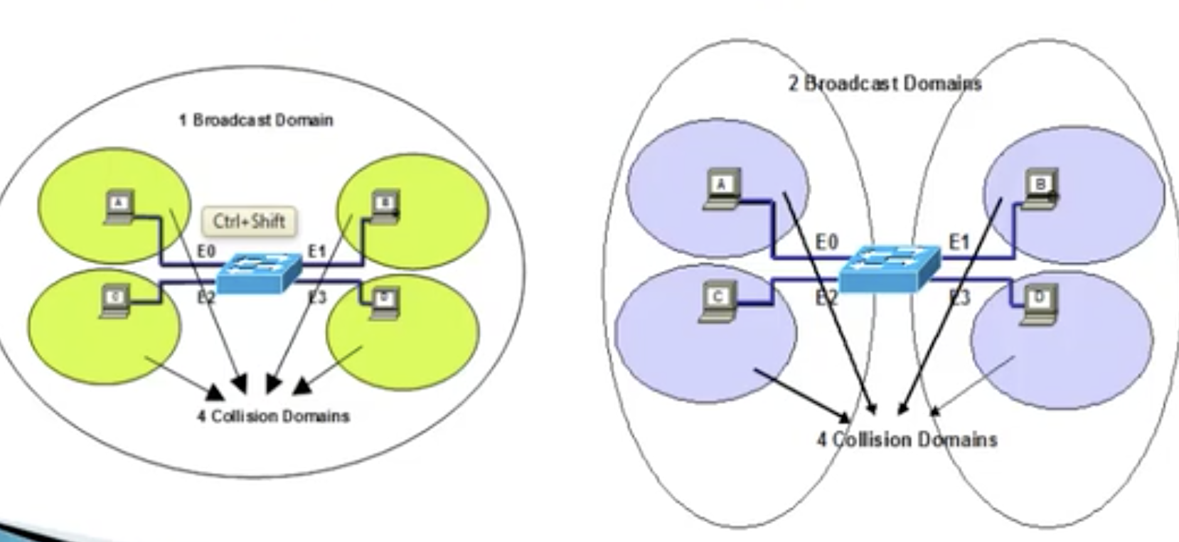
- Also provides a layer 2 security
- vlan 1 is the default VLAN (only one VLAN).
- We can create VLANs from 2 to 1001 (the range).
- Can be configured on manageable switches only.
Minimising the number of broadcasts: why?
- Switches forward packets based on MAC addresses. Assume two devices are trying to communicate through a switch. If there is no entry of the destination in its MAC address table, it is going to send a broadcast.
- Now assume there are multiple switches connected to each other, and in each LAN, there are going to be 50 different devices connected to the switch for a department in a company.
- What you do is just to assign subnets, like 192.168.1.0 and 192.168.2.0 and 192.168.3.0 and so on.
- When a switch does a broadcast, it also does to other switches connected to it (just like in the diagram below) until the broadcast reaches a router.
- Ands if other switches receive the broadcast, it is going to broadcast locally as well, to all 50 devices connected to it, which is unnecessary because the destination is already inside the LAN of the original switch. So the bigger the size of the LAN, the bigger the size of broadcast domain. You need a solution for this: VLAN.
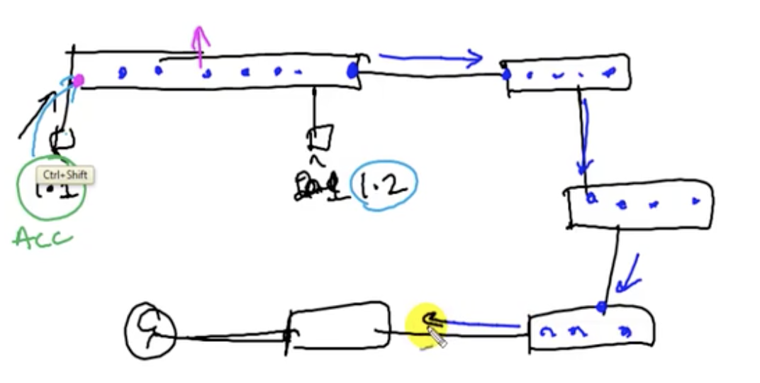
Minimising the number of broadcasts: how
Benefits of VLANs
- What you are going to do is to divide one single broadcast domain into multiple partitions into a 'virtual' LAN.
- So if a broadcast happens, now the broadcast does not go to all the devices in the real LAN, but only inside the virtual LAN. The number of broadcast packets is greatly reduced. This is beneficial because the performance of a network is reduced by the broadcasts.
Benefits of VLANs
- Limits the number of broadcasts
- Better performance
- Security (because the broadcast packets are only sent inside of VLAN now)
14.2: VLAN and Trunking: Static VLAN
Types of VLAN
1. Static VLAN:
VLAN configuration on switch
1. VLAN creation
1. Static VLAN:
- works based on port numbers
- need to manually assign a port on a switch to a VLAN
- also called port-based VLANs
- one port can be a member of only one VLAN
- works based on MAC addresses.
VLAN configuration on switch
1. VLAN creation
- configure terminal
- vlan <no> (2-1001)
- name <VLAN name>
- exit
- configure terminal
- interface <interface type> <interface number> (registers the ports one by one) OR:
- interface range <interface type><interface number ',' OR '-' interface number> (gives the range ports)
- switchport mode access
- switchport access VLAN <number>
- show vlan (brief)
- just follow the same steps in 2 with a different VLAN number. Then the specified ports will be reassigned.
VLAN creation on CLI
Static VLAN: details
- Say you've got a switch and there are 24 ports. By default all the ports are in VLAN 1.
- Next, you can create VLANs and give them names and number.
- Assume port 1-3 and port 7-8 are to belong to sales dept. You need to identify the computers belonging to these ports to put them manually into the VLAN named 'sales'. Then, broadcasts are restricted inside that group of ports only. It's as if there are multiple LANs.
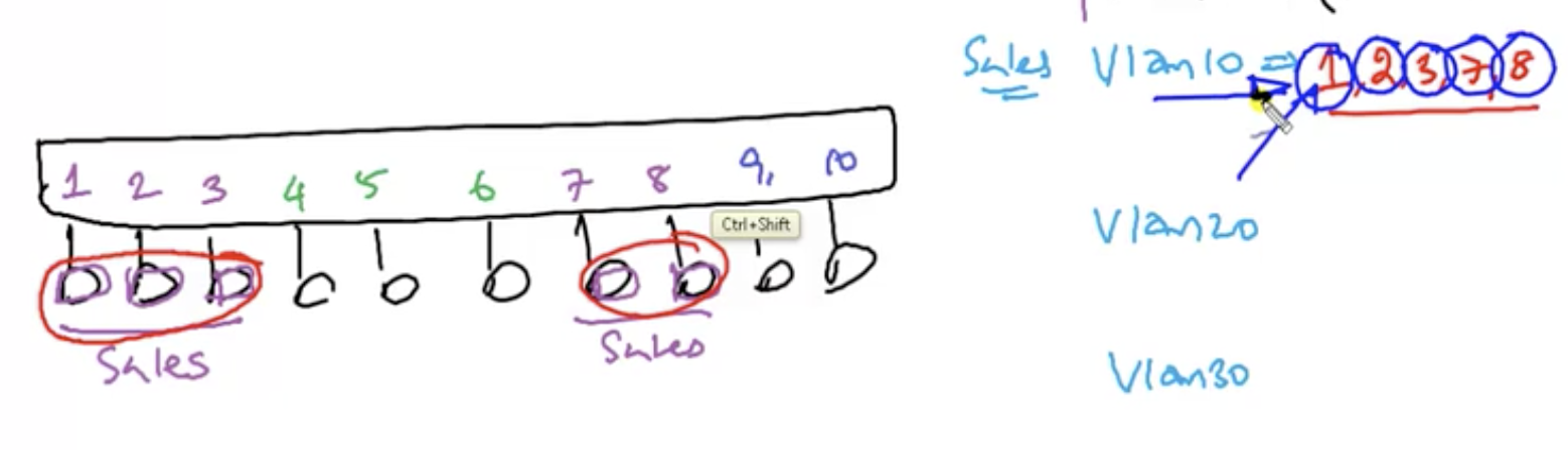
Assigning ports to vlan 10 (sales)
Reassigning ports to another VLAN
14.3: VLAN and Trunking: Dynamic VLAN
Basics
- Dynamic VLANs are based on the MAC address of a computer. Say, you've got a switch. To use VLAN, you need to have VMPS to maintain a database that contains a table of MAC addresses and corresponding VLANs. Say you've got a device newly connecting to the switch. Then the switch is going to query the VMPS asking which VLAN to assign to that device (MAC address). Then VMPS is going to reply with the relevant VLAN information. The important difference from static VLAN is that it does not matter which port the same device connects to again; VMPS will always assign the same VLAN to that device because the assignment is based on MAC addresses.VMPS adds extra overhead to server admins.
- Switch automatically assigns a port to a VLAN
- Each port can be a member of multiple VLANs.
- For dynamic VLAN configuration, a software called VMPS(VLAN membership policy server) is needed.
- Generally not used in today's networks
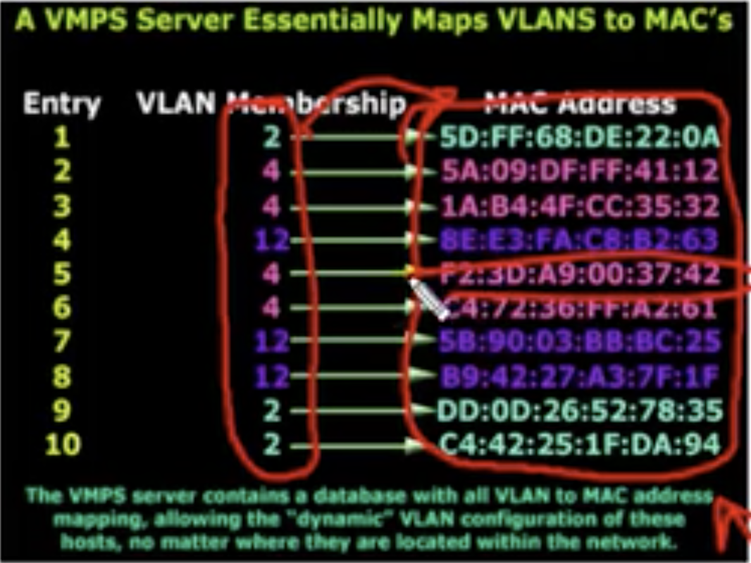
14.4: VLAN and Trunking: Trunking
The reason for trunking
In trunking, a single VLAN can span over multiple switches.
In trunking, a single VLAN can span over multiple switches.
- Say, there are floors in a building. There are people working in the IT department in the 1st floor, 3rd, 5th, 6th floor and so on.
- As they are far from each other physically, connecting them all to the same switch is nearly possible.
- But if you really wanna do that, you need to do some cabling to get them together. Physically connecting everyone to the same switch requires some additional cabling.
- But that's too tedious; you don't wanna do it that way. So you just decide to connect each group users to each switch in each floor and to connect the switches together to extend the LAN.
- The thing is that the users in the same VLAN can actually use different switches using the concept explained above.
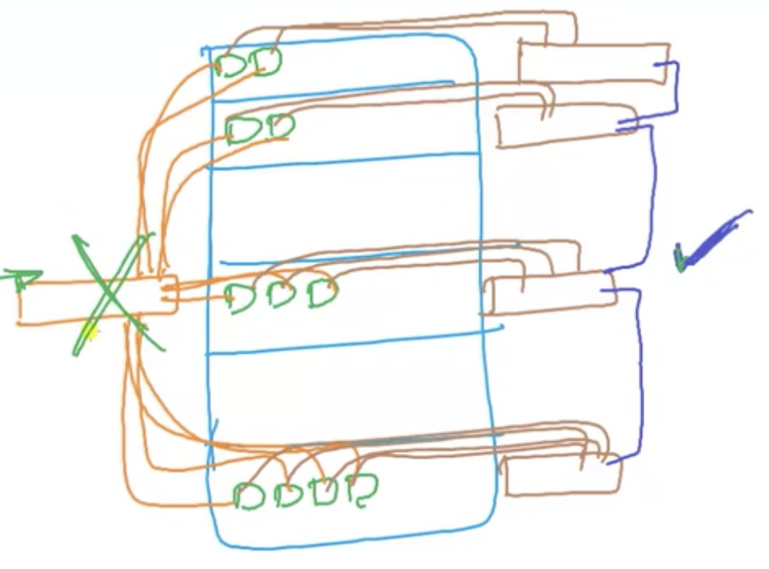
|
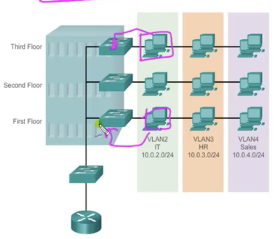
|
Trunking: details
There are two ways of doing implementing the above diagram.
1. Passing VLAN traffic using separate links for each VLAN
Types of links/ports (look at the diagram below)
1. Access link
There are two ways of doing implementing the above diagram.
1. Passing VLAN traffic using separate links for each VLAN
- So VLAN 1 user will send a traffic through VLAN 1 connection across the switches to reach another VLAN 1 user.
- The same thing happens for other VLAN users as well.
- But this is not a scalable solution; it's hard to build like 20 VLANs between switches.
- VLAN users can communicate across different switches through one line of connection without interference between different VLANs.
Types of links/ports (look at the diagram below)
1. Access link
- used to end devices (hosts or router)
- belongs to only one VLAN
- Does not belong to any VLAN
- carries multiple VLANs traffic
- links between two switches.
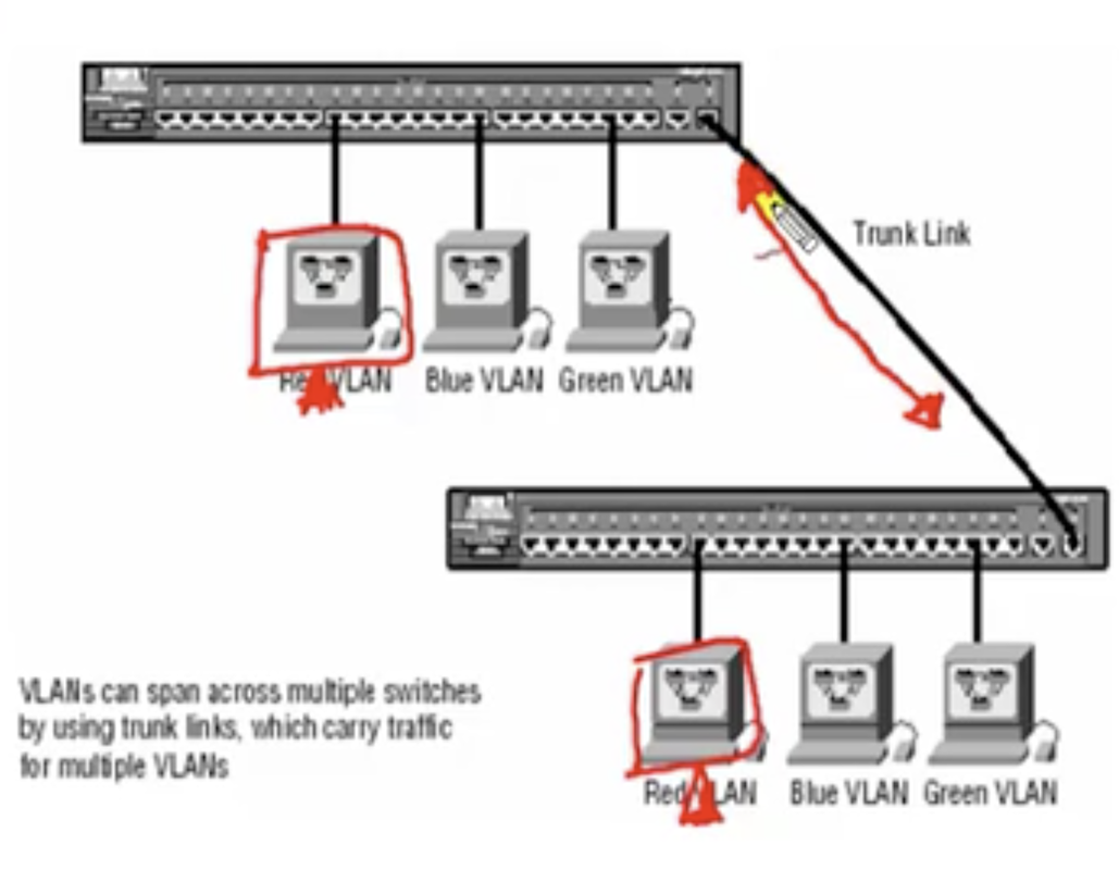
Now there is a question: how does trunk link differentiate different VLANs?: Frame tagging.
- A tag is added before a frame is sent, and it is removed once it is received on trunk link.
- Frame tagging happens only in the trunk links.
- What switch does is that when a packet is sent from a device, it is going to add a tag to a frame before sending the packet over the link. The tag contains VLAN ID with VLAN number.
- SW1 (in the diagram) knows about its local VLANs information. But SW2 does not.
- So SW1 can do it. Once the packet is received by the SW2, it is going see the tag information and realizes which VLAN it belongs to, and remove the tag and send the frame as a normal packet.
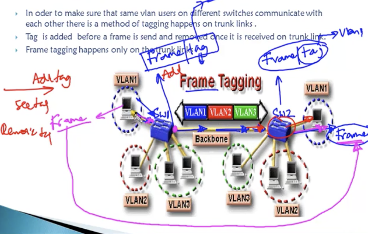
14.5: VLAN and Trunking: Trunking lab
Trunking protocols: ISL and IEEE 802.1Q
ISL
Trunk configuration
ISL
- Cisco proprietary, but mostly no more used. In today's networks, no more used. Even Cisco used IEEE 802.1Q.
- works with Ethernet, token ring, FDDI (Token ring and FDDI are no more used)
- It adds 30 bytes of tag (extra overhead on switches)
- All VLAN traffic is tagged.
- Open standard
- Works only on Ethernet
- Only 4 Byte tag will be added to original frame.
Trunk configuration
- switch(config)# interface <interface type> <interface number>
- switch(config-if)# switchport mode trunk (tells the switch to use the interface as a trunk port)
- siwthc(config-if)# switchport trunk encapsulation dot1q OR ISL
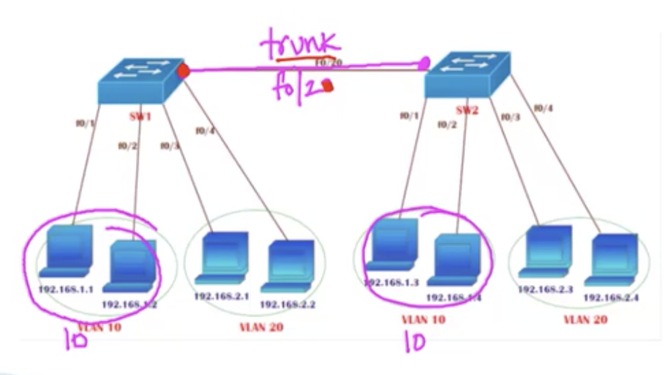
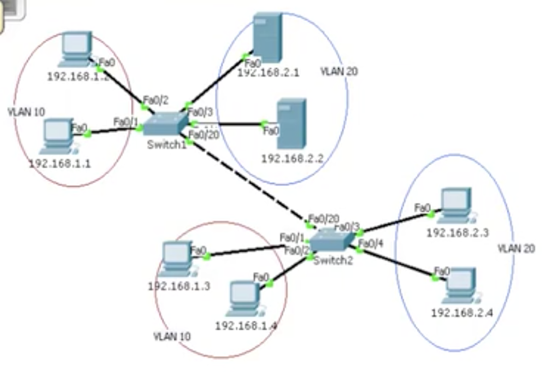
Trunking lab topology
- Assume that the topology has already been configured as above.
- Notice that a trunk link needs to be configured between the two switches above.
- If you try to ping from, for example, 192.168.1.1 to 192.168.1.3, it would NOT work because the trunk link has not been configured.
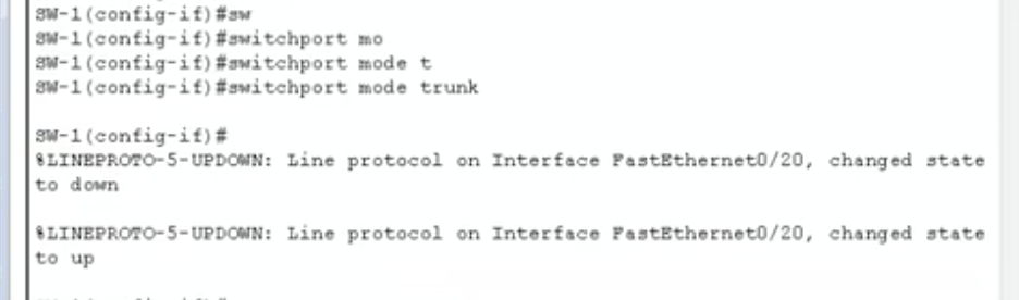
trunk link configuration on SW1
|
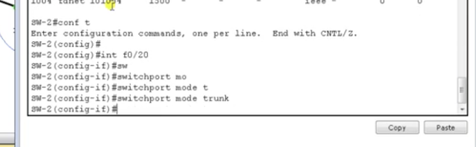
trunk link configuration on SW2
|
See that you need to configure trunk link on the interfaces of both switches. And just for the sake of the packet tracer, it does not support encapsulation, so you do not need to worry about encapsulation commands as of now.
Now, verify using: show interfaces trunk. It is going to tell you about the ports that have been configured with trunking, active VLANs, and the range of VLANS allowed on trunk. You can check also by pinging across switches.
Now, verify using: show interfaces trunk. It is going to tell you about the ports that have been configured with trunking, active VLANs, and the range of VLANS allowed on trunk. You can check also by pinging across switches.
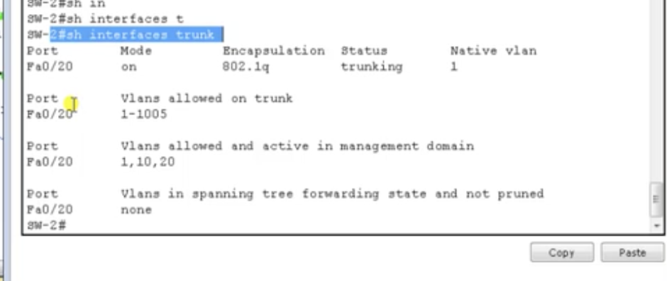
show interfaces trunk
And lastly, remember this:all different VLANs must be in different subnets. And trunking must be manually configured. It's not something automatic.
14.6: VLAN and Trunking: interVLAN routing (1) - obsolete method
The need for interVLAN routing
1. Packets in one VLAN cannot cross into another VLAn.
2. To transport packet between VLANs, you must use a Layer 3 device.
3. The router must have a physical or logical connection to each VLAN so that i can forward packets between them (even if they are different).
4. This is known as interVLAN routing.
5. InterVLAN routing can be performed by an external router that connects to each of the VLANs on a switch.
On the router, you can make some access control list, which can filter the traffic.
Inter-VLAN routing methods
1. Separate physical gateway for each VLAN on router (old, obsolete)
Say you've got three different VLANs in one LAN managed by switch A. And many devices are connected to that switch. If you have three VLANs, you need three separate gateways to support each VLAN.
2. Using sub-interfaces
You can configure a trunk link, and use sub-interfaces (only one connection)
3. Using layer 3 switch (mostly used)
Multilayer switch is used.
- From previous chapters, you know that computers that are in the same VLAN but belong to different switches can communicate each other through a trunk link.
- But what if other computers that belong to another VLAN also want to communicate with a computer across a switch?
- Then, you route the communication with a router.
1. Packets in one VLAN cannot cross into another VLAn.
2. To transport packet between VLANs, you must use a Layer 3 device.
3. The router must have a physical or logical connection to each VLAN so that i can forward packets between them (even if they are different).
4. This is known as interVLAN routing.
5. InterVLAN routing can be performed by an external router that connects to each of the VLANs on a switch.
On the router, you can make some access control list, which can filter the traffic.
Inter-VLAN routing methods
1. Separate physical gateway for each VLAN on router (old, obsolete)
Say you've got three different VLANs in one LAN managed by switch A. And many devices are connected to that switch. If you have three VLANs, you need three separate gateways to support each VLAN.
2. Using sub-interfaces
You can configure a trunk link, and use sub-interfaces (only one connection)
3. Using layer 3 switch (mostly used)
Multilayer switch is used.
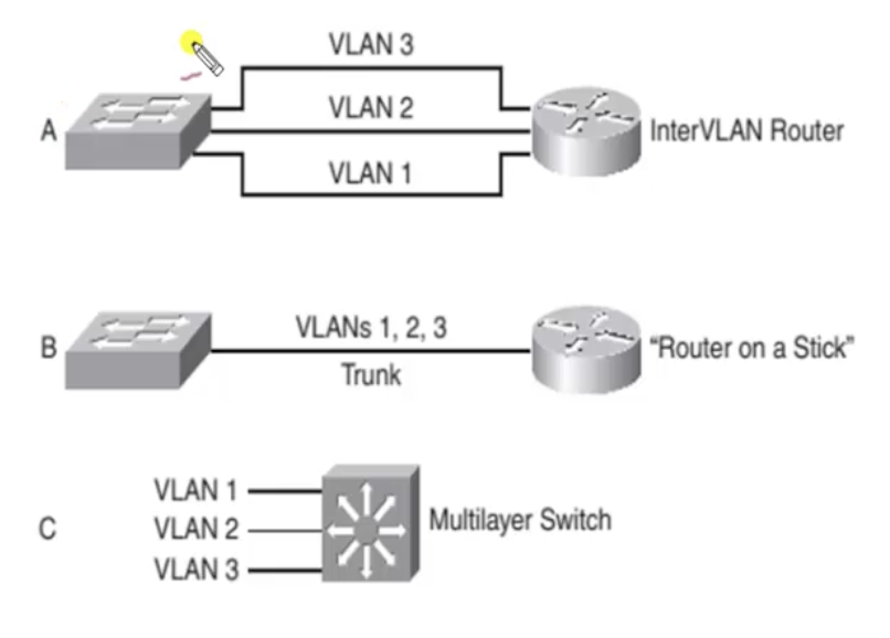
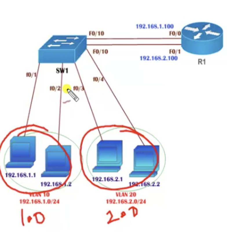
Topology for the lab
You want these two different VLANs to communicate with each other. Then you need a router with two subnet gateways. n VLANs, n gateways.
InterVLAN hands-on configuration
1. Make sure the basic connections have been correctly established and the IP addresses are correctly assigned.
2. Make sure the port numbers 1 and 2 are configured for VLAN 10 and 3 and 4 are configured for VLAN 20 in the switch.
3. Add the gateways. Now:
InterVLAN hands-on configuration
1. Make sure the basic connections have been correctly established and the IP addresses are correctly assigned.
2. Make sure the port numbers 1 and 2 are configured for VLAN 10 and 3 and 4 are configured for VLAN 20 in the switch.
3. Add the gateways. Now:
- Ensure that the interfaces F0/10 and F0/11 (written incorrectly in the diagram) belong to VLAN 10 and VLAN 20 respectively as well. The interfaces F0/0 and F0/1 on the router must also belong to VLAN 10 and VLAN 20 respectively; in sum, each VLAN has to be one subnet and cannot be in the subnet of another VLAN.
- Lastly, check by using ping.
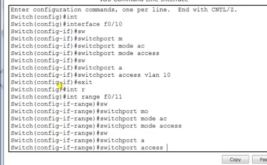
Assign IP addresses to interfaces on the switch
|
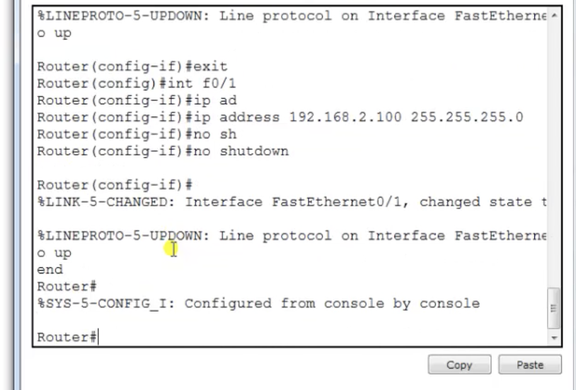
Assign IP addresses to interfaces on the router
|
14.7: VLAN and Trunking: interVLAN routing (2) - using sub-interfaces
The drawback of the previous method is that for every single VLAN, you need a separate gateway, which would be tedious for big number of VLANs.
Details
Configuration by steps
1. Assign port numbers to each VLAN
Drawbacks
Details
- So what you are going to do is to divide an interface into sub-interfaces (logically). For example if you have an interface f0/0 on the router connecting to the switch, it is going to be divided .into f0/0.10, f0/0.20, .... and so on. Each sub-interface acts as one interface for each VLAN. It is going to minimize the number of gateways required.
- Trunk link is required.
Configuration by steps
1. Assign port numbers to each VLAN
- See previous chapters.
- configure terminal
- interface f0/10
- switchport mode trunk (This means this port is now going to carry multiple VLAN traffics.)
- switchport trunk encapsulation dot1q (not needed for the packet tracer)
- no shutdown (before creating sub-interfaces. ensure that the interface is not off)
- no ip address (no ip address before making sub-interfaces as well)
- interface f0/0.10 (that's it. You've made one sub-interface). The number that follows the dot could be anything, but for ease of understanding, making it the corresponding VLAN number would be useful.
- encapsulation dot1Q 10 (this argument is the VLAN number)
- ip address 192.168.1.100 255.255.255.0 (assign a gateway address for this sub-interface)
- do the same thing for other sub-interfaces, and ensure that the ip address is in the same subnet as VLAN 20 (192.168.2.0/24)
- show ip interface brief will tell you about the sub-interfaces made.
Drawbacks
- If you wanna communicate across VLANs, the traffic should go through the router that is going to send again to a different VLAN.
- The router is going to make some latency because of the router lookup.
14.8: VLAN and Trunking: interVLAN routing (3) - Multilayer switch
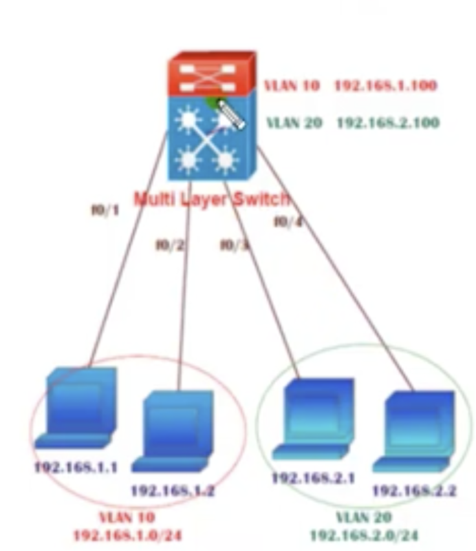
A multilayer switch can be used as a router as well.
The same thing happens on the CLI on the switch at first:
1. Assign ports to VLAN
2. Just assign an IP address to the VLAN, and that is going to make the gateway for VLAN 10.
Notice that there are hardly physical interfaces needed to configure the settings in mtl.
Not only that, Layer 3 Port on MLS could also be used to connect to a router.
The same thing happens on the CLI on the switch at first:
1. Assign ports to VLAN
- configure terminal
- interfcae range f0/1 - 2 (and for other ports)
- switchport mode access
- switchport access vlan 10 (and for other VLAN numbers)
- verify using show vlan.
2. Just assign an IP address to the VLAN, and that is going to make the gateway for VLAN 10.
- interface vlan 10
- ip adddress 192.168.1.100 255.255.255.0
- no shutdown
- exit (do the same for other VLANs)
- ip routing (on some platforms, routing may not be on by default, so just enable this)
Notice that there are hardly physical interfaces needed to configure the settings in mtl.
Not only that, Layer 3 Port on MLS could also be used to connect to a router.
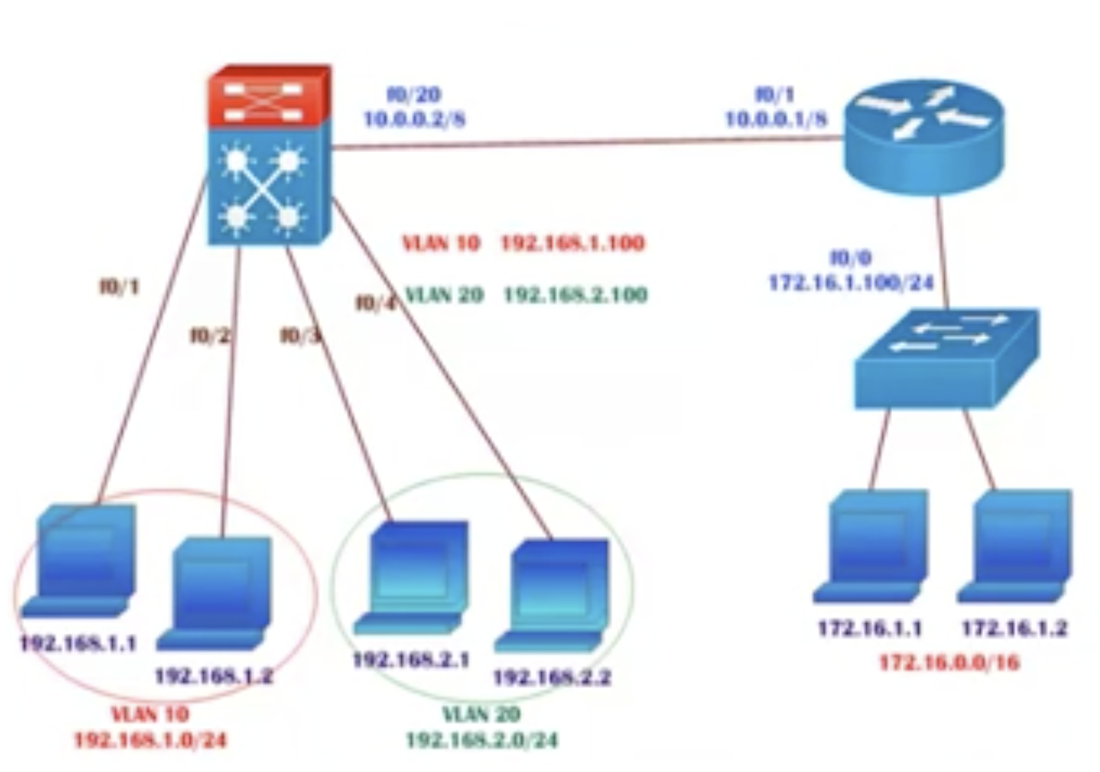
1. Assign an IP address to a port to which you are going to connect a router.
1. No switchport and assign an IP address on a specific interface in the multilayer switch
Option 2: assign an interface to a VLAN, and an IP address to a VLAN (instead of assigning to a physical interface)
1. Go to the MLS and assign an interface to a VLAN.
- Switch(config)#interface f0/20
- ip address 10.0.0.2 255.0.0.0 -> But it's not working because by default this port is a layer 2 port (this means this port is only going to identify MAC addresses). So what are you gonna do? Two possible solutions: (1) Change it from L2 to L3. (2) Assign a port to a VLAN
1. No switchport and assign an IP address on a specific interface in the multilayer switch
- Switch(config)#interface f0/20
- no switchport
- ip address 10.0.0.2 255.0.0.0
- verify using show ip interface brief
- for example: Switch(config)#router eigrp 100
- network 10.0.0.0
- network 192.168.1.0
- network 192.168.2.0
- and also configure on the router (right side on the diagram):
- Router(config)# router eigrp 100
- network 172.16.0.0
- nettwork 10.0.0.0
- Check using ip eigrp neighbors and show ip route eigrp
Option 2: assign an interface to a VLAN, and an IP address to a VLAN (instead of assigning to a physical interface)
1. Go to the MLS and assign an interface to a VLAN.
- interface f0/20
- switchport access vlan 100
- verify using show vlan
- interface vlan 100
- ip address 10.0.0.1 255.0.0.0
- no shutdown
- verify using show ip interface brief
14.9: VLAN and Trunking: Extended and voice VLAN
- Originally, Ethernet VLANs only supported the range from 2 to 1001.
- For some reason the lecturer says the Cisco Catalyst switches have supported up to 1024 VLANs historically (but I think it's right. It's just that I cannot understand it).
- But 802.1Q (used for trunking) includes a 12-bit VLAN ID field (which allows up to 4096 VLANs)
- Cisco defines the VLANs between 1025 and 4096 as extended-range VLANs. You can use these VLANs to add more VLANs in the network.
Most Cisco catalyst switches support extended-range VLANs under the following restriction:
1. VTP(VLAN Trunk Protocol) cannot be used for VLAN management (VTP must configured in transparent mode or off. So if you are using anything other than this, extended range VLANs are not going to work)
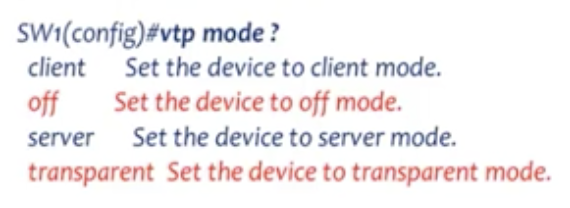
|
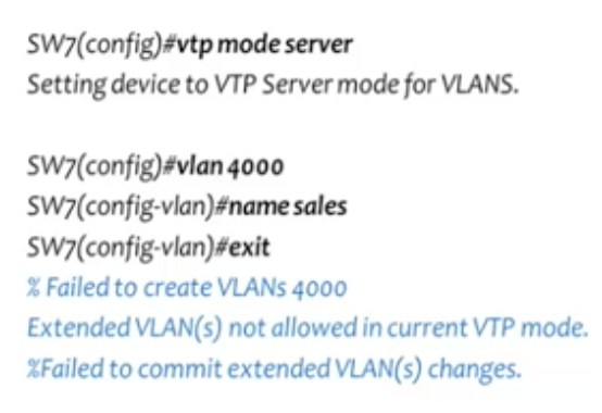
Notice that the extended-range VLAN configuration fails when you configure the VTP mode as server, but not 'off' or 'transparent'.
|
2. The spanning-tree extended system ID feature (AKA MAC address reduction) must be enabled.
- This feature is enabled by default, and you cannot disable it.
- This feature is a combination of priority value (used for trunking) + VLAN information.
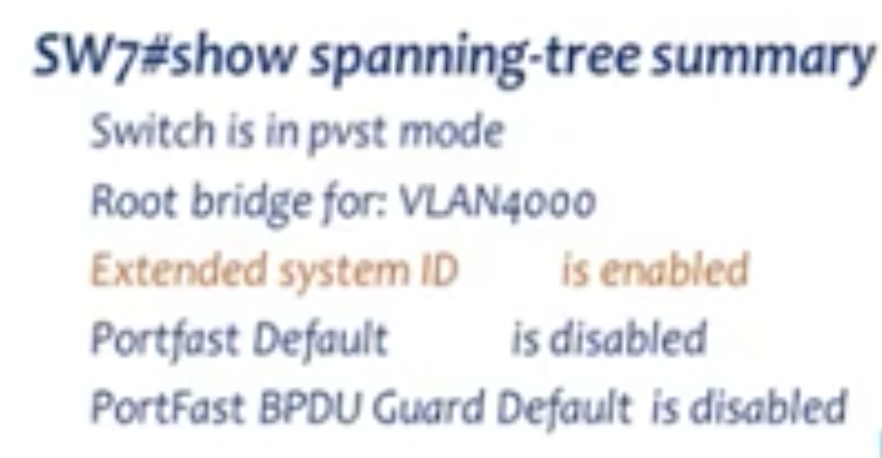
confirm that it is enabled by default.
|
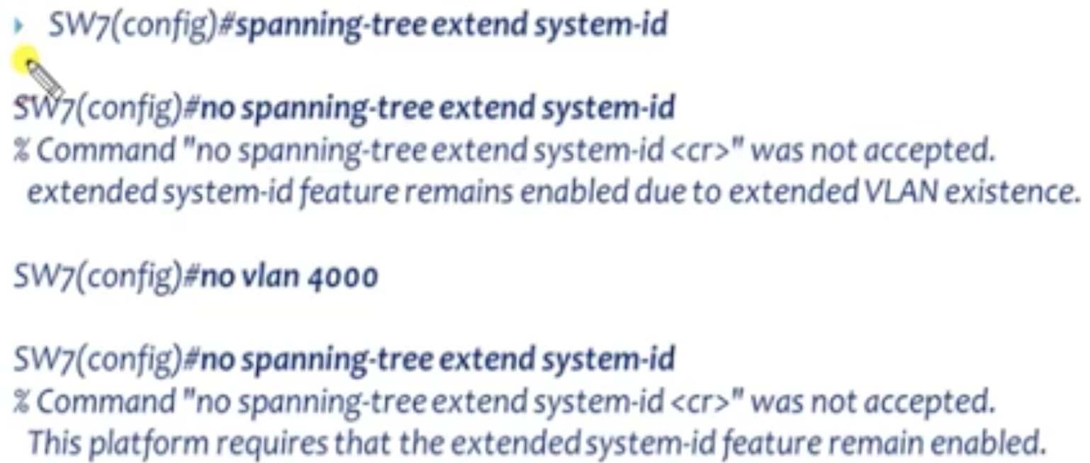
no sappning-tree extended system-id command is not accepted.
|
Voice VLAN
This is for the case when you have an IP phone in your network which is going to send the wire signals through the switch. And you want to configure a VLAN for that, and this is called Voice VLAN.
Default VLAN configurations
This is for the case when you have an IP phone in your network which is going to send the wire signals through the switch. And you want to configure a VLAN for that, and this is called Voice VLAN.
- Voice VLAN feature enables access port to carry IP voice traffic from an IP phone.
- Switch can connect to an IP Phone to carry IP voice traffic. IP phone has two ports to connect to a switch and a computer.
- Cisco IP Phone contains an integrated three-port 10/100 switch.
Default VLAN configurations
- The voice VLAN feature is disabled by default.
- You should configure voice VLAN on switch access ports
- The voice VLAN should be present and active on the switch for the IP phone to correctly communicate on the voice VLAN.
- Use: show vlan privileged EXEC to see if the VLAN is present
- The PORt Fast feature is automatically enabled when voice VLAN is configured (covered in more detail in later chapters).
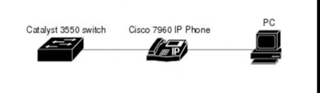
Voice VLAN configuration
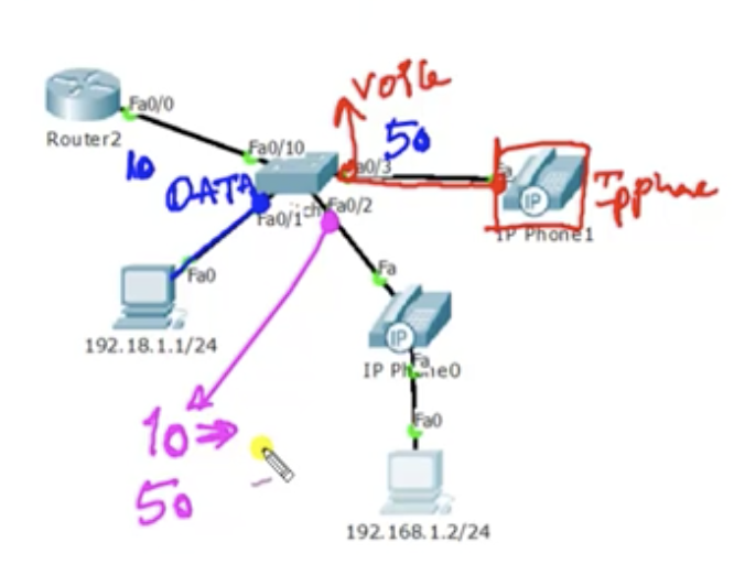
In this scenario, we use VLAN 10 for data, and VLAN 50 for voice. Now, see that VLAN 50 can be used for the port that is only connected to the IP phone (rightmost in the diagram). And If you are only using a computer, that's just going to be VLAN 10. But notice that VLAN 10 and VLAN 50 can be used for the same single port to connect to an IP phone that is connected to a computer. Do two jobs.
1. Create VLANs
On the switch,
On the switch,
On the switch,
As seen, Fa0/2 interface belongs to both VLAN 10 and 50.
1. Create VLANs
On the switch,
- configure terminal
- vlan 10
- name DATA
- exit
- vlan 50
- name VOICE
- exit
On the switch,
- interface f0/1
- switchport mode access
- switchport access vlan 10
- exit
- interfcae f0/3
- switchport mode access
- swtichport voice vlan 50
- exit
On the switch,
- configure terminal
- interface f0/2
- switchport mode access
- switchport access vlan 10
- swithport voice vlan 50
- end
As seen, Fa0/2 interface belongs to both VLAN 10 and 50.
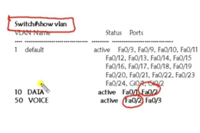
14.10: VLAN and Trunking: Native VLAN
Basics
- If a packet is received on a dot1q link that does not have VLAN tagged, it is assume that it belongs to a native VLAN.
- Default native vlan is VLAN 1
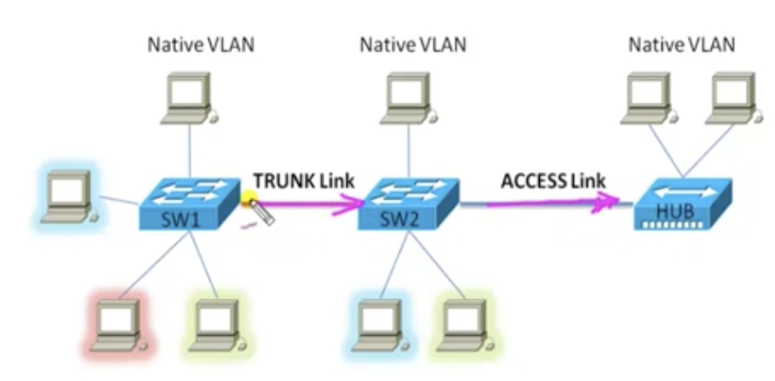
For example, you've got a hub connected to SW2 via access link. And SW1 and SW2 are connected via trunk link.
Native VLAN: best practices
Native VLAN configuration
Before configuration, make sure that you already have your trunk link ready between the two switches that you are going to use.
On both switches,
Verify using:
- By default there is a 802.1Q protocol on the trunk link. And say, there is a VLAN 10 connected to SW1, and as we know, when the traffic from VLAN 10 goes through the trunk link, a tag is going to be added to the frame, so that SW2 understands which VLAN the traffic should go to.
- But there are some cases where you receive the frames without a tag, for example from a hub.
- In such case, the traffic is going to be sent to the native VLANs only. That is the default behaviour.
Native VLAN: best practices
- The best practice is to configure the native VLAN ID to VLAN 666 (or if you want, any other VLAN numbers not in use) and to ensure that this VLAN is not used anywhere in the network.
- No port should be assigned to the native VLAN
- An attacker who attempts to use the VLAN hopping attack will end up in a dead VLAN that has no hosts to leverage.
Native VLAN configuration
Before configuration, make sure that you already have your trunk link ready between the two switches that you are going to use.
On both switches,
- configure terminal
- vlan 999 (notice there is no port assigned to this vlan)
- end
- int f0/20
- switchport mode trunk
- switchport trunk native vlan 999
Verify using:
- show interfaces trunk (pic showing native vlan number 999 because it's been changed)
- show interfaces f0/20 switchport (See the section: trunking native mode VLAN)
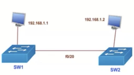
|
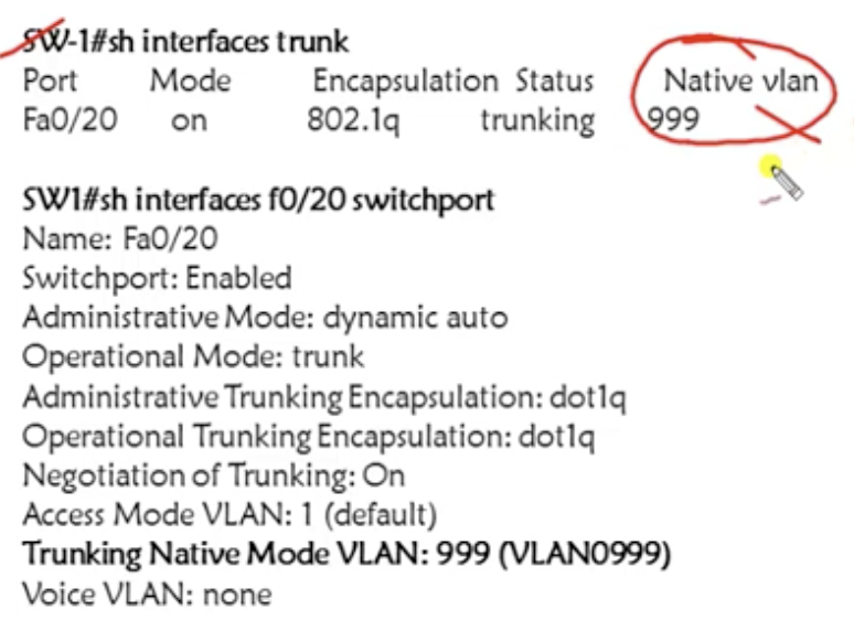
Verification
|
15.1: VLAN Trunking Protocol (VTP): Basics
Basics
- VTP is a Cisco proprietary protocol
- used to share the VLAN configurations with multiple switches and to maintain consistency throughout that network
- You have VLAN 10, 20 30, 40, 50 and 60. Six different VLANs. All different VLANs are applied to different switches. The problem is that you should go to each switch to create a new VLAN. And also if you want to modify VLAN, you should go to each switch. This is something not scalable.
- So instead of that, if you create a VLAN in some switch, you want all other switches in its network to come to know about that VLAN information. If you modify/remove anything about VLAN on that switch, the same happens. This concept is the VTP.
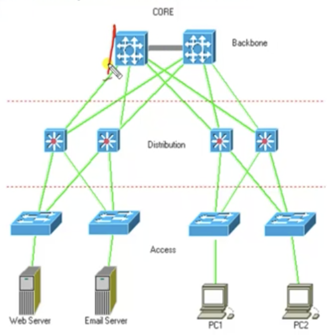
Details
VTP modes
1. Server mode (just like read and write)
- VTP manages the addition, deletion, and renaming of VLANs across the network from a central point of control.
- Information will be passed only if switches are connected with FastEthernet or higher ports (at least 100 Mbps port)
- Trunk links must be preconfigured between switches
- switches should be configured with the same domain (= name for VTP)
- Domain
VTP modes
1. Server mode (just like read and write)
- Default mode for all switches
- Can create, modify, and delete VLAN configuraitons
- Synchronizes VLAN configurations (The server router sends out the information to its neighbors, and they will send to their neighbors). So all the clients will have the same VLAN information.
- Sends and forwards (not the client's own information, but new information that it has got from somewhere) advertisements
- Saves configurations in NVRAM permanently
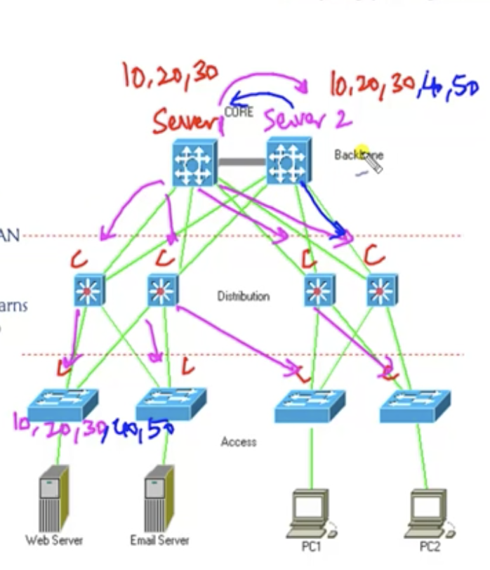
2. Client mode (Read only)
- cannot add, modify and delete its VLAN configurations
- does not store its VLAN configuration information in the NVRAM. instead, learns it from the server every time it boots up
- Forwards advertisements
- Synchronizes VLAN configurations
- Does not save in NVRAM. Gets the information on VLAN configurations the server
- More similar to server mode, but does not synchronize (the switch itself will not try to take the information as its own) but forwards (passes onto the next switch) VLAN configurations. Therefore it is used in the circumstances where you don't want certain switch to know VLAN information, but just forward it.
- can add, modify and delete VLAN configurations
- forwards advertisements
- saves configuration in NVRAM
15.2: VLAN Trunking Protocol (VTP): Verify VTP lab pre-requirements
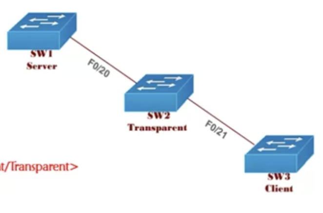
Lab topology
1. Configure trunking
On switch 1 (and for other switches you know what to do),
on a switch,
4. The VLANs should be seen in the client swtich if the information is correctly synchronized, and the transparent switch should not know about VLAN created from the server
5. Any VLANs created in SW2 should not be shared with other switches
On switch 1 (and for other switches you know what to do),
- configure terminal
- interface f0/20
- switchport mode trunk encapsulation dot1q
- switchport mode trunk
- show interfaces trunk
on a switch,
- VTP domain CCIE
- vtp password < password > (not necessary)
- vtp version 2 (not necessary)
- vtp mode <server / client / transparent > (choose one. by default, all the switches are server switches. You can configure them to be different things.)
- vtp pruning
- and verify using: show vtp status & show vtp password
- VTP is off by default
- Once enabled, VTP by default uses version 1 only
4. The VLANs should be seen in the client swtich if the information is correctly synchronized, and the transparent switch should not know about VLAN created from the server
5. Any VLANs created in SW2 should not be shared with other switches
15.2: VLAN Trunking Protocol (VTP): VTP configuration

1. Configure VTP (assume trunking is done)
Switch 1
Switch 1
- configure terminal
- vtp domain VTPTEST (anything)
- vtp mode server
- vtp password cisco
- vtp version 2
- show vtp status
- configure terminal
- vtp domain VTPTEST
- vtp mode transparent
- vtp password cisco
- vtp version 2
- vtp domain VTPTEST
- vtp password cisco
- vtp version 2
- vtp mode client
- show vtp status
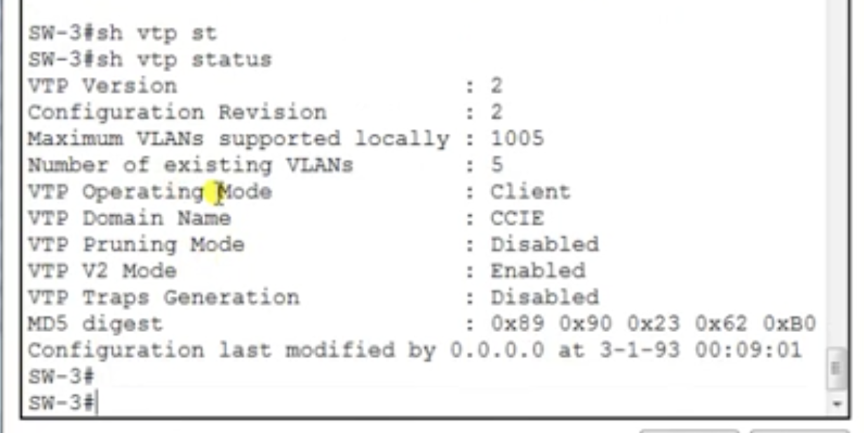
2. Configure VLANs
Switch 1
Switch 1
- configure terminal
- vlan 10
- vlan 20
- vlan 30
- show vlan (now it has to show vlan 10, vlan 20, and vlan 30)
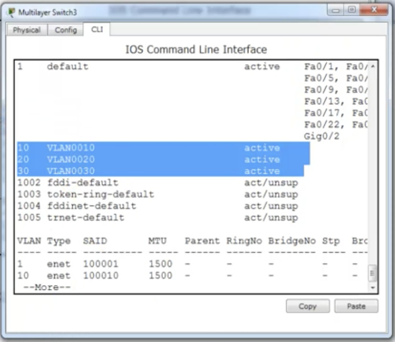
Switch 3 has been synced with VLAN info
|
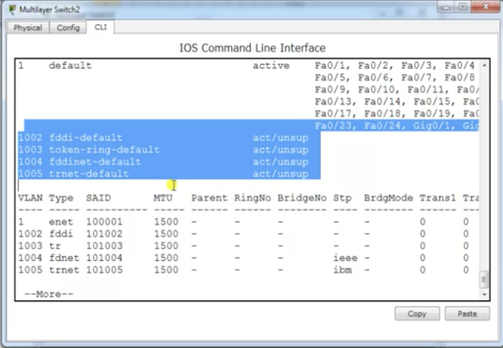
Switch 2 does NOT sync VLAN info for itself
|
Note: these things must match to have a proper protocol
3. Create VLANs on the transparent switch to check it does not send to other switches
Switch 2
4. Additional commands for verification
- Domain name
- Password
- Version (1 or 2)
3. Create VLANs on the transparent switch to check it does not send to other switches
Switch 2
- vlan 100
- vlan 200
- vlan 300
- show vlan (does not show vlan 100, 200, 300)
4. Additional commands for verification
- show vtp password
- show vtp status (shows version, configuration revision count(increments every time there is a configuration. But it stays as 0 on a transparent mode switch), VTP domain name and so on)
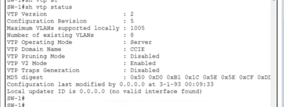
show vtp status
Configuration revision number
Ensure a new switch has VTP revision number 0 before adding it to a network. Say, one of your switches in your network was down while VTP has been configured on your network. Now you boot up your switch. There are a few ways you could safely add the switch to ensure that the configuration revision number is not synced wrongly:
Otherwise, if the configuration revision number in that switch booting up is like 100 and the existing VTP domain has the configuration revision number as 55, the revision number in the whole VTP domain, once the switch is connected to that domain, will be synced to 100. So MAKE SURE that you set the revision number as 0 in the switch that you are newly adding to a VTP domain.
Deleting Vlan.dat file
on a switch that's to be added to a VTP domain,
- VTP switches use an index called VTP configuration revision number to keep track of the most recent information (this number is also synced across server & client switches)
- The VTP advertisement process always starts with configuration revision number 0
- When the subsequent changes are made on a VTP server, the revision number is incremented before the advertisements are sent.
Ensure a new switch has VTP revision number 0 before adding it to a network. Say, one of your switches in your network was down while VTP has been configured on your network. Now you boot up your switch. There are a few ways you could safely add the switch to ensure that the configuration revision number is not synced wrongly:
- Change the switch's VTP mode to transparent and then change the mode back to server
- Change the switch's VTP domain to a bogus name (a nonexistent VTP domain) and then change the VTP domain back to the original name
- Delete Vlan.dat file inside the flash and reload to set the configuration revision number 0
Otherwise, if the configuration revision number in that switch booting up is like 100 and the existing VTP domain has the configuration revision number as 55, the revision number in the whole VTP domain, once the switch is connected to that domain, will be synced to 100. So MAKE SURE that you set the revision number as 0 in the switch that you are newly adding to a VTP domain.
Deleting Vlan.dat file
on a switch that's to be added to a VTP domain,
- show flash
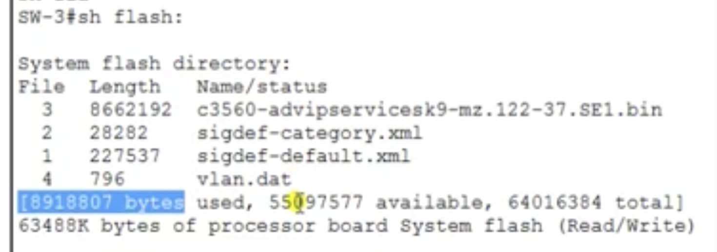
- delete vlan.dat

- show flash again, and it must not show vlan.dat
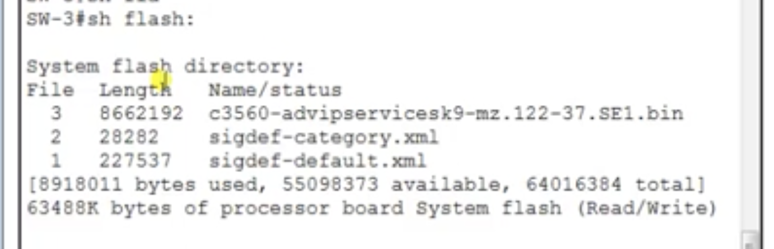
- reload (your switch is not yet connected to the VTP domain yet)
- show vtp status and check the configuration revision number is 0.
- configure VTP according to a specification and trunking and all that
- Now, connect.
- show vtp status and check if the configuration revision number is synced from the server
16.1 Spanning tree protocol: why do we need spanning-tree protocol
Bridging loops
- It is a redundant link between switches
- There is also a possibility for loops to be created when switches do broadcasts
Explained with example
You've got 40 devices connected in a LAN and you've got a switch that only has 24 ports. What you could do is to use one more switch that would probably have 24 ports and connect the rest of switches to that switch. And we use cross cable to connect between the switches. That's how you extend a LAN. If there 500 devices in a LAN, that does not mean you are using a 500-ports switch.
Now what if a link between switches go down? The users on switch 1 would not be able to talk to talk across the switches. So because there is a single point to the failure, what you could do is to add one more link (total two) between the switches.
This adds 'redundancy' (as a positive term) because if one of the links is down, the other would still be up for the connection.
But the problem is this redundancy could create a loop. So if both links are working, switch 1 would broadcast, and the broadcast would go through - let's say - link 1, to the ports on switch 2 as well. Now switch 2 would broadcast back to switch 2 through the link 2, and that's going to repeat forever. This continuous loop is called a broadcast storm.
Because of this, the mac address table would also not be stable. There is also a possibility with multiple frame transmissions.
In sum, if you use a redundant link between switches to extend a LAN, it would provide redundancy which is good, but this may create:
You need a solution for this.
You've got 40 devices connected in a LAN and you've got a switch that only has 24 ports. What you could do is to use one more switch that would probably have 24 ports and connect the rest of switches to that switch. And we use cross cable to connect between the switches. That's how you extend a LAN. If there 500 devices in a LAN, that does not mean you are using a 500-ports switch.
Now what if a link between switches go down? The users on switch 1 would not be able to talk to talk across the switches. So because there is a single point to the failure, what you could do is to add one more link (total two) between the switches.
This adds 'redundancy' (as a positive term) because if one of the links is down, the other would still be up for the connection.
But the problem is this redundancy could create a loop. So if both links are working, switch 1 would broadcast, and the broadcast would go through - let's say - link 1, to the ports on switch 2 as well. Now switch 2 would broadcast back to switch 2 through the link 2, and that's going to repeat forever. This continuous loop is called a broadcast storm.
Because of this, the mac address table would also not be stable. There is also a possibility with multiple frame transmissions.
In sum, if you use a redundant link between switches to extend a LAN, it would provide redundancy which is good, but this may create:
- Broadcast storms
- Mac address table instability
- Multiple frame transmissions
You need a solution for this.
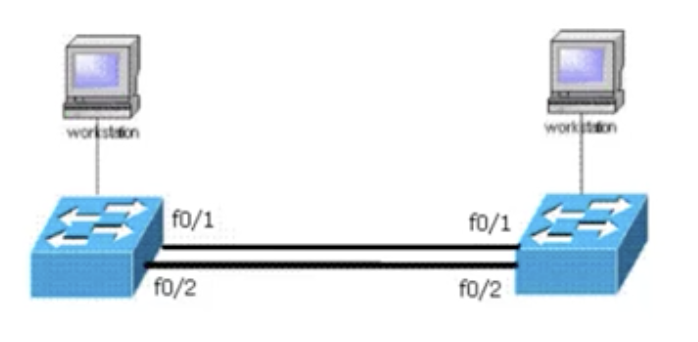
Possible solutions for bridging loops
Role of STP
- Provide only one link between switches (but it is not going to create redundancy in case of link failure. Not recommended)
- Shutdown the extra link temporarily
- Manually (shutdown command)
- Automatically block extra links (done by STP)
Role of STP
- STP is going to find redundant links in a network.
- It would ensure that if any of the links is in a forwarding state (transferral of data), the rest of the links would be in a block state automatically. This is the job of STP.
- In case, one of the links goes down, STP would automatically make another link the 'forwarding' link, because now the previous forwarding link is down.
16.2 Spanning tree protocol: How STP works (1)
Basics
- STP stops the lops which occur when you have multiple links between switches
- STP avoids broadcast storms, multiple frame copies and database instability
- STP is a open standard (IEEE 802.ID)
- STP is enabled by default on all Cisco Catalyst switches
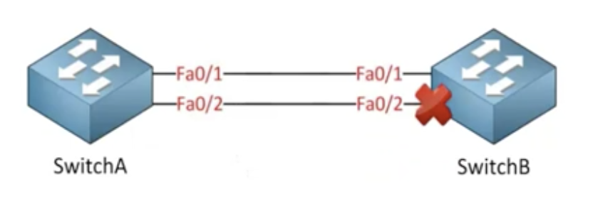
STP in 3 steps with an example:
You've got a user in SW2 and SW3. And if a broadcast starts from SW2, no matter which direction, it is going to generate a loop.
1. Selecting the root bridge
You've got a user in SW2 and SW3. And if a broadcast starts from SW2, no matter which direction, it is going to generate a loop.
1. Selecting the root bridge
- Root bridge is the bridge with the best (lowest) bridge ID.
- Bridge ID = (Priority, first two bytes) + (MAC address of the switch, last 6 bytes).
- The default priority value for a switch is 32768.
- whichever switch that has the least value would be the best switch. For example, SW has 32768, SW2 has 4096, and SW3 has 8192 as the priority ID. Then SW2 is going to be the root bridge. But what if all the switches have the same value?
- Then you look at the MAC address. Every switch has its own mac address (verified with show version command). Whichever switch that has the least MAC will become the root bridge.
- Switches are going to work this out themselves by advertisements and agree on one common root bridge.
- Out of all the switches in the network, one is elected as a root bridge that becomes the focal point in the network.
- Every switch would send hello packets (BPDU = Bridge Protocol Data Unit) every 2 secs.
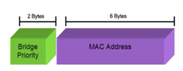
|
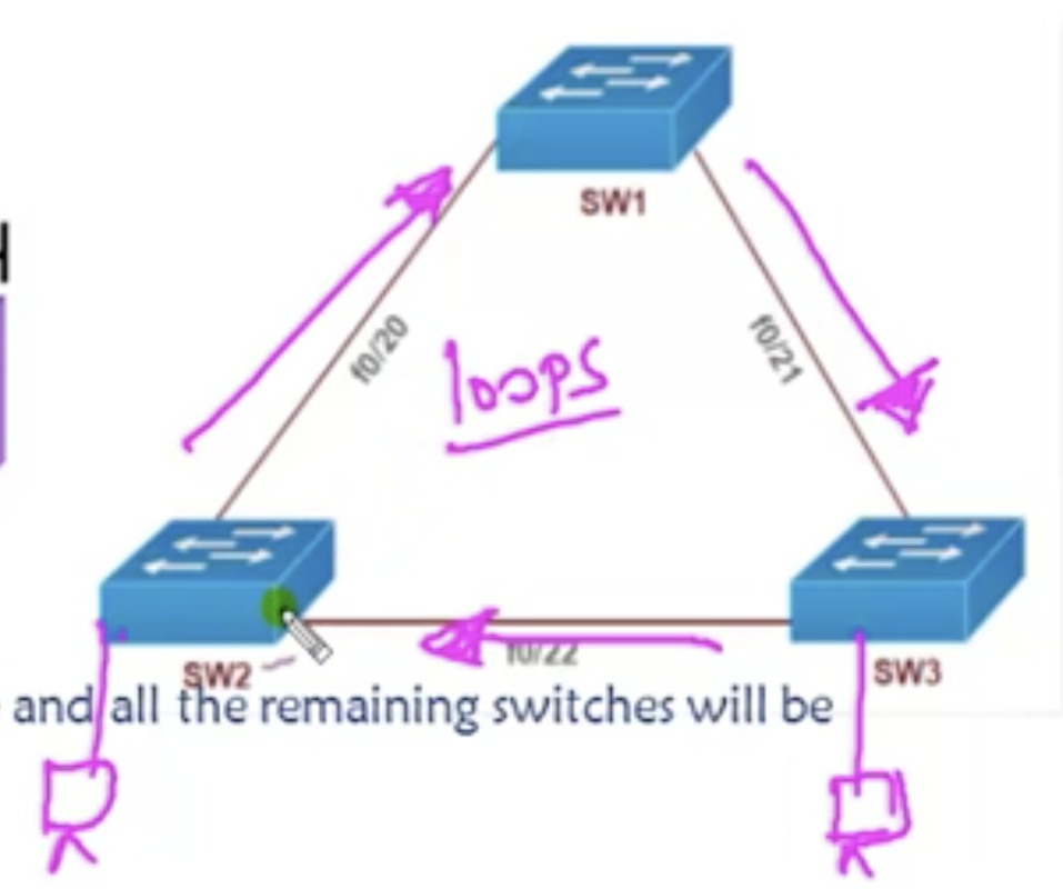
|
2. Selecting the root port
- Every non-root bridge looks for the best way to go to root bridge.
- The best way is the shortest path to the root bridge.
- Conditions for the shortest path:
- last cost (link speed. Something different from when you talk about administrative distances and advertising costs). The default speed for the links between switches is 100 mbps. Thus each link would have the cost of 19.
- the lowest forwarding switch ID (priority + MAC address)
- lowest forwarding physical port number
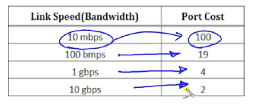
but what if all the links have the tying cost? Now you have to look at the forwarding switch ID (= bridge ID).
- The port to which there is the lowest forwarding switch ID would be chosen.
- For example, if the link speed in the topology in below picture is the same across the network and the switch ID of the rightmost switch is 40000 and that of leftmost switch is 30000, the root port of the bottommost switch would be the port that connects to the leftmost one, not the rightmost one.
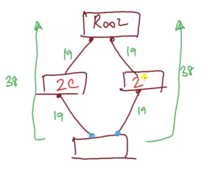
- If there is a tie in the bridge IDs across the neighbors of the switch that you are trying to decide the root port for, you look at the upstream port number (NOT the local port number. You are not looking at the port attached to your own switch that you are deciding the bridge ID for. You are looking at the port number of your directly connected switch (neighbor).
- The least port number will be preferred. So for example, if there are port numbers 23 and 24 that you are connecting to (regardless of your local ports), you are going to choose the root port (your own port) that is connected with the port number 23 in your directly connected switch.
16.3 Spanning tree protocol: How STP works (2)
3. Selecting the designated port ('forwarding' ports) and non-designated port('blocking' ports)
- The ports in the root bridge connected to other switches will always be forwarding ports. You should NOT have any blocking ports in the root bridge.
- The root ports in the rest of the switches will always be forwarding ports because they are the way to the shortest path to the root bridge.
- Some ports in the the rest of the ports would be in a blocking state. The decision is made based on the same condition to choose a root port but EXCEPT the forwarding bridge ID. So after looking at the cost, you look at the MAC addresses of each port. The port with a lower MAC address (of a local port number) would win, so the other port would be in a blocking state.
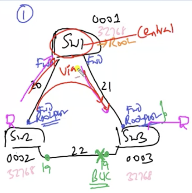
Notice that when broadcast starts from SW2, it is going to be blocked at the port where the 'X' sign is.
BPDU (Bridge protocol data unit, AKA hello packets)
Port states in STP
BPDU (Bridge protocol data unit, AKA hello packets)
- All switches exchange through BPDU that contains information regarding ports, switches, port priority and addresses.
- Hello packets are sent every 2 sec
- At the time of initial installation, every switch will by default advertise itself as the root bridge to each other and will come to a conclusion to choose only one switch as the root bridge after comparison.
- Once the root bridge has been elected, it is going to send the hello packets to all switches. The normal switches will not, then, send hello packets.
- Max age (dead): 20 secs. In case a link goes down, the network waits for 20 secs before it starts another route for forwarding.
- The entire STP process happens in 30 secs total:
- listening time: 15 secs.
- learning time: 15 secs.
Port states in STP
- Blocking: 20 secs or no limits
- Listening: 15 secs
- Learning:15 secs
- Forwarding: no limits
- Disable: no limits
- Default convergence time in STP: 30 secs (if a local port fails) or 50 secs (if a link fails)
16.4 Spanning tree protocol: STP lab
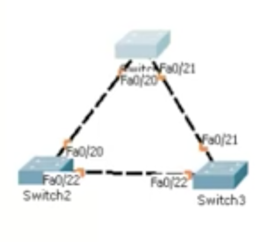
Topology right after the Initial installation. The connection points are coloured orange, which means the connection is still being prepared.
|
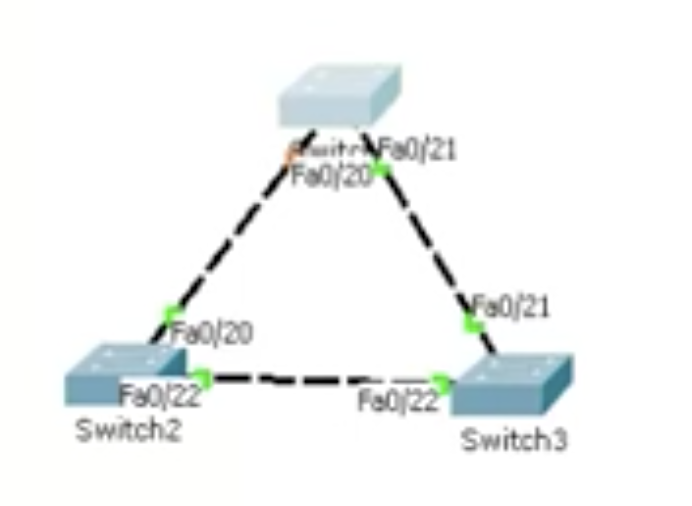
after the listening and learning states. The STP is ready to be used. One orange dot represents the port that's in a blocking state.
|
show spanning-tree
This command shows interfaces and their states, and relevant bridge IDs and the root ID.
This command shows interfaces and their states, and relevant bridge IDs and the root ID.
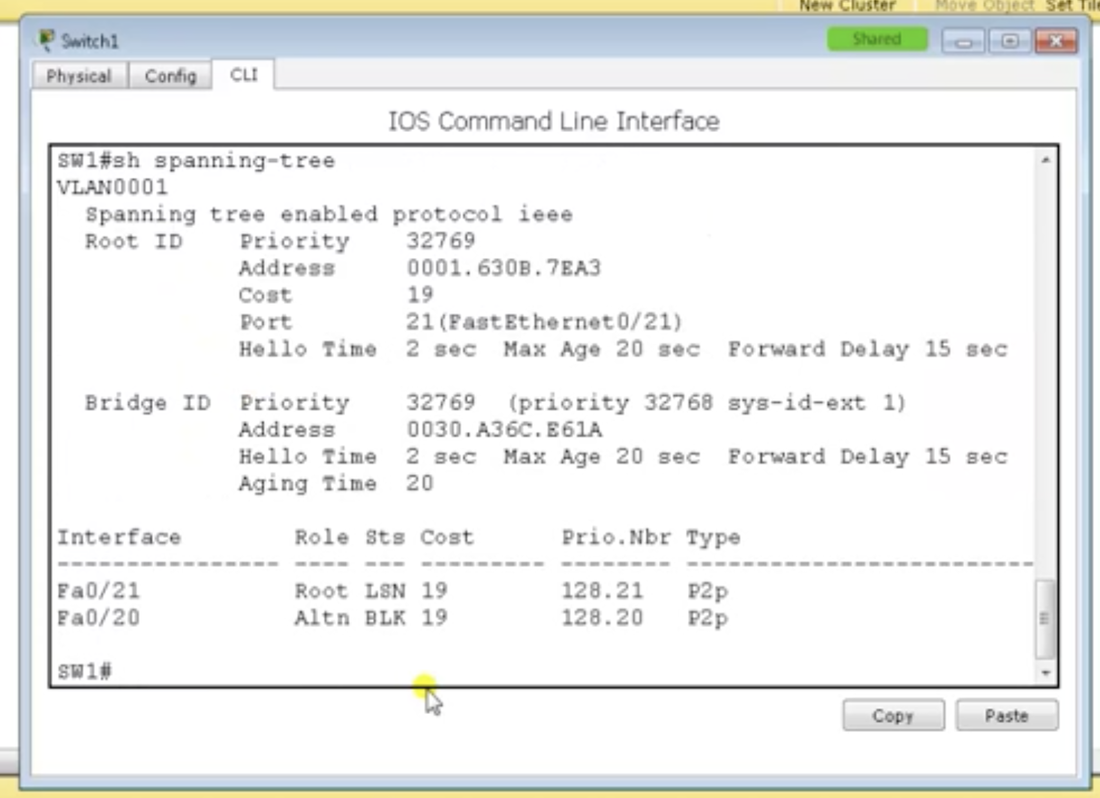
Switch 1 after few seconds of initial installation. One of the ports is still in a learning state, and the other blocking.
|
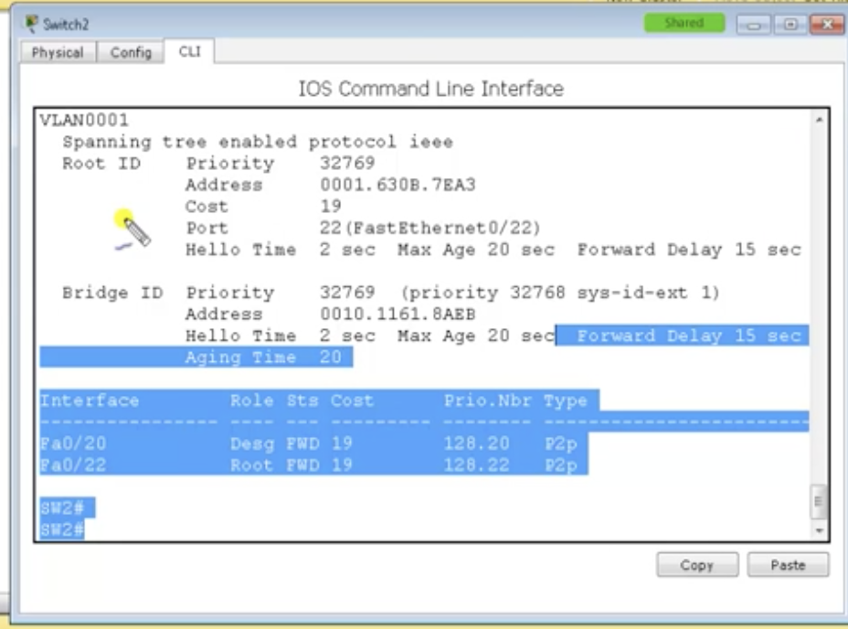
Switch 2.
|
Root ID: The root bridge
Bridge ID: The local switch on which you are viewing a CLI right now
Bridge ID: The local switch on which you are viewing a CLI right now
Finding the root bridge
- The topmost switch is definitely NOT the root bridge because it has a blocking state port.
- show spanning-tree on some switch and look at the section port: XX.
- Then go to the link that has that port. If the port number is the same at the ends of a link, you do show spanning-tree on both switches and compare the Root ID with the bridge ID. If you go onto the root bridge switch, it is going to tell you that it is the root bridge switch.
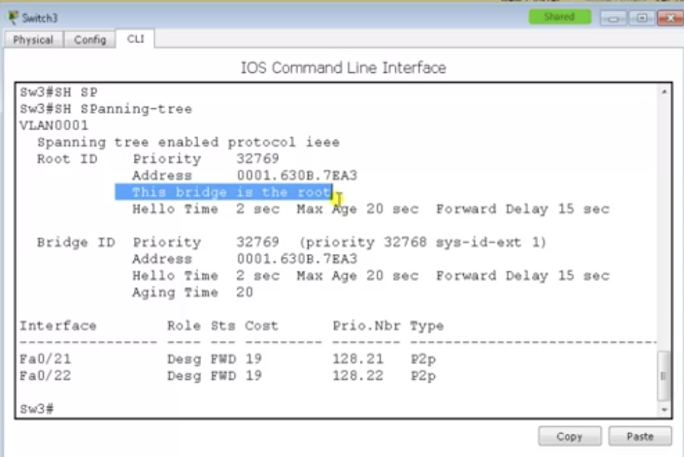
Note:
Convergence test
- Every root port is a forwarding port
- But not every forwarding port is a root port
Convergence test
- If the right port at the topmost switch fails, the left port which is currently in a blocking state would go through listening and learning stages (total 30 secs) and the should become a root port because that's now only the shortest way from the topmost switch to the rightmost switch that is the root bridge.
- if you boot up the right port again, the left port at the topmost switch would immediately go blocking state. And the right port would go through listening and learning states to again become the root port of that switch.
16.5 Spanning tree protocol: Spanning tree - PortFast
Why need PortFast? with an example
whenever you provide a connection to a port on a switch, the port goes through listening and learning states (30 secs). This is the default behaviour. After 30 secs of confirming that there is no possibility of making loops, the port is going to be open for connection.
There are some services that may get affected by that. Say, you've got a DHCP server connected to the switch. And whenever you power on a PC connected to the switch, it is going to send a broadcast request, requesting the DHCP server to assign an IP address for it. But the switch is not going to forward that request until 30 secs elapse. So because of that time, there may be some problem at the DHCP server about receiving the request. So you don't want that.
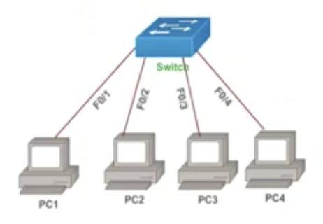
So, to fix this problem, you could skip the listening and learning states using a feature called PortFast on certain ports.
Basics
PortFast configuration
PortFast on specific ports
Basics
- Cisco-proprietary enhancement to spanning tree
- helps speed up network convergence on access ports
- PortFast causes a port to enter the spanning-tree forwarding state immediately, bypassing listening and learning states.
- PortFast should be used only when connecting a single end station (like a PC) to a switch port.
- If you enable PortFast on a port connected to another networking device, such as a switch, you are creating a network loop.
PortFast configuration
PortFast on specific ports
- configure terminal
- interface range f0/1 - 10
- configure terminal
- spanning-tree portfast default
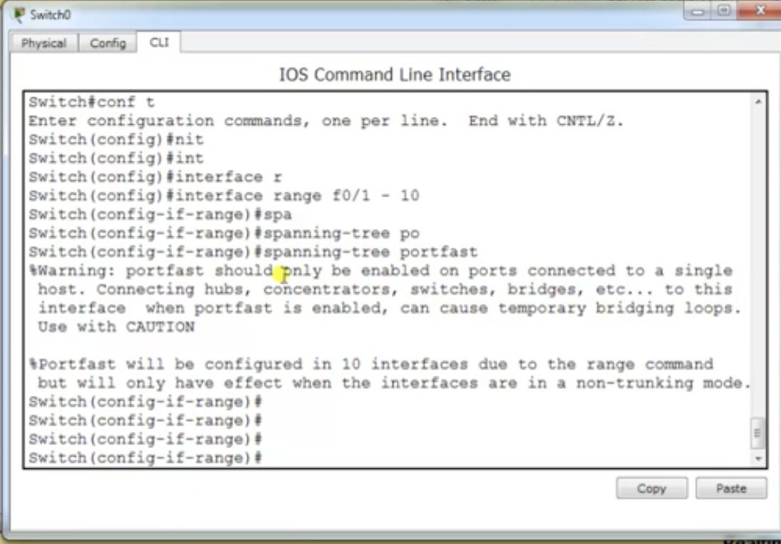
16.6 Spanning tree protocol: UplinkFast & BackboneFast
Basics
- Legacy / Cisco proprietary feature
- UplinkFast is for speeding up the convergence time when a direct link to an upstream switch
- When UplinkFast is enabled, it is enabled for the entire switch and all VLANs.
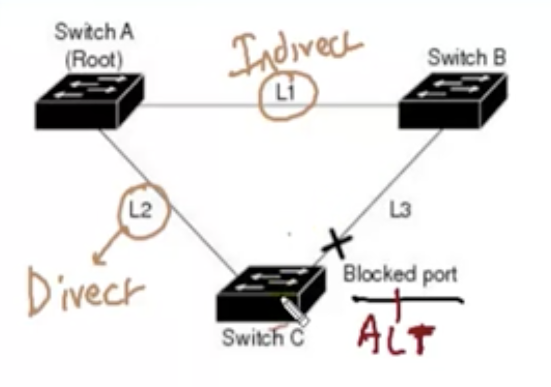
Explained with an example
UplinkFast configuration
on a switch that is not the root bridge switch,
- Say, STP has made the port with 'X' sign a blocking state.
- Direct link: the link to the switch where the block port is
- Indirect link: the link to switches that do NOT have the blocked port
- If the direct link (L2) goes down, it is going to take 30 secs of convergence time by default.
- if your indirect link (L1) fails, it is going to take 50 secs of default convergence time (blocking state for 20 secs, and 15 secs of listening state, and another 15 secs for learning state.)
- If you use UplinkFast: If a direct link fails, the switch with the blocked port will update itself within 1 sec.
- If you use BackboneFast: If an indirect link fails, the switch attached to that link will send some notification about that status to the rest of the switches. The switch with the blocked port will then NOT need the blocking (down) state for 20 secs. Instead it could directly go into the listening & learning state (total 30 secs).
UplinkFast configuration
on a switch that is not the root bridge switch,
- configure terminal
- spanning-tree uplinkfast
- show spanning-tree (verify)
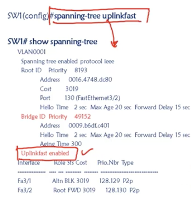
Note:
BackboneFast configuration
- spanning-tree uplinkfast is not allowed on the root bridge switch.
- With the configuration, the bridge priority is changed to 49,152 so that this switch will NOT be selected as root
BackboneFast configuration
- configure terminal
- spanning-tree backbonefast
- show spanning-tree backbonefast (verify)
16.7 Spanning tree protocol: RSTP 802.1w
Basics
Configuration
On a switch,
- RSTP: Rapid spanning tree protocol.
- 802.1w is a standard way of speeding up STP convergence time.
- It contains inbuilt features of PortFast, UplinkFast (for a direct link), and BackboneFast (for a indirect link).
- Path calculation goes the same as STP (the three conditions).
Configuration
On a switch,
- configure terminal
- spanning-tree mode rapid-pvst
- show spanning-tree
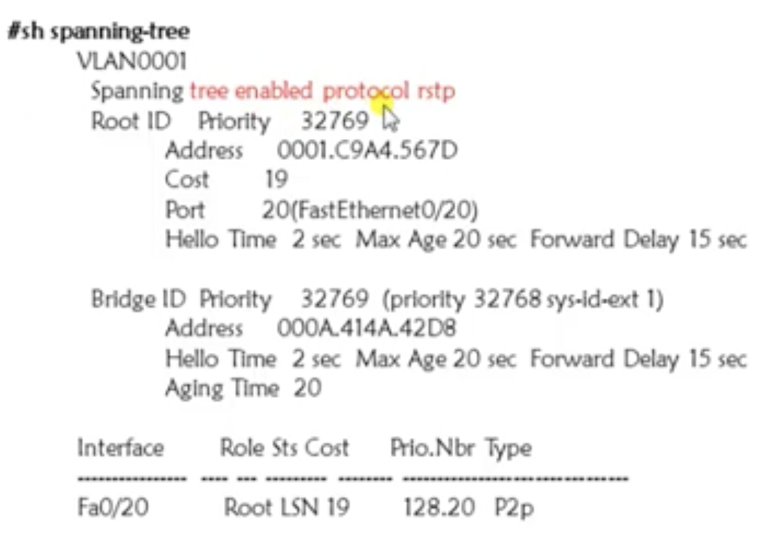
RSTP port states: comparing 802.1d and 802.1w port states
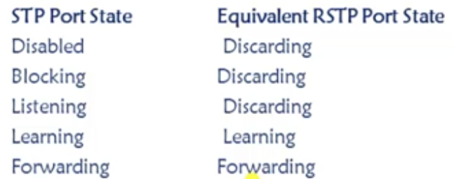
In case of RSTP, there are only three status of ports.
- Discarding: Frames are dropped and no addresses are learned (link down / blocking / during sync)
- Learning: frames are dropped, but addresses are learned.
- Forwarding: frames are forwarded.
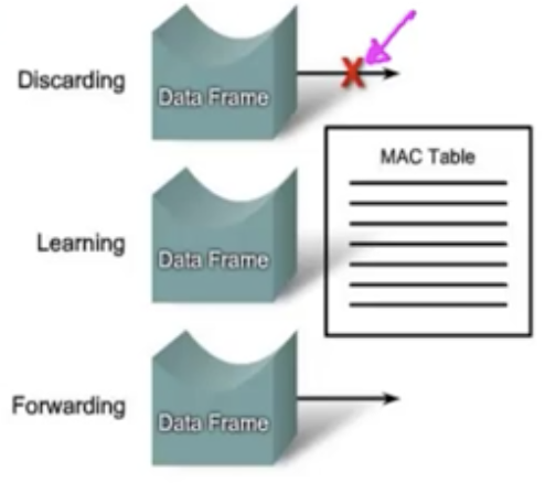
RSTP synchronization
In case of normal STP, the default convergence time (for a direct link) is 30 secs. In case of RSTP, it does not work that way.
It works based on two different kinds of messages:
Proposal message and agreement message
In case of normal STP, the default convergence time (for a direct link) is 30 secs. In case of RSTP, it does not work that way.
It works based on two different kinds of messages:
Proposal message and agreement message
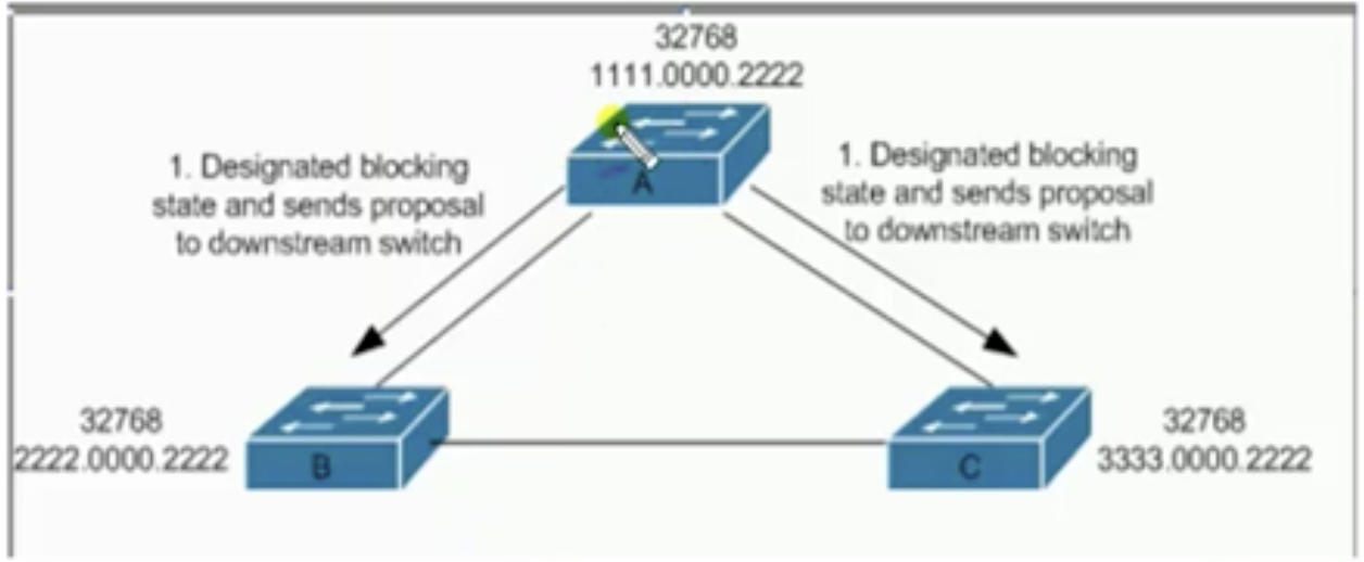

- The MAC address of the switch A starts with 1111 and B starts with 2222 and C, 3333. According to the STP process, switch A is going to be the root bridge switch.
- It is going to send 'proposal messages' to switch A and switch B.
- Then, switch A expects an 'agreement message' from these switches.
- Switch B is going to compare its own bridge ID information with Switch A. After the comparison, switch B is going to send an agreement message to Switch A.
- After that, Switch B is going to set its root port as the port that's got the shortest path to switch A.
- The same thing happens between Switch A and Switch C as well.
- This process is almost the same as STP, but it happens a lot faster than that.
RSTP port roles
- Root port: the best pat to the root (same as STP)
- Designated port: same role as wit STP
- Alternate port: a backup to the designated port
- Disabled port: not used in the spanning tree
- Edge port: connected only to an end user
Alternate port
- A backup to the root port
- Less desirable path to the root
- operates in the discarding state
- Basically functions the same as UplinkFast(legacy)
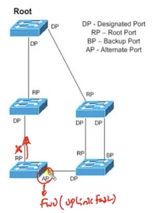
Backup port
- The backup port applies only when a single switch has two links to the same segment (collision domain)
- To have two links to the same collision domain, the switch must be attached to a hub (generally).
- A backup to the designated port
- Multiple links attached to the same network segment
- Activated only if primary designated port fails.
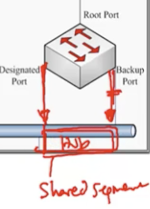
Edge port
BPDU differences in RSTP
RSTP configuration
on every switch,
RSTP port costs
- Equivalent to PortFast in STP. It is the port on the switch that allows PortFast function.
- Connected only to an end user
- Maintain edge status as long as no BPDU received (with BPDU filter = Edge ports)
BPDU differences in RSTP
- In a regular STP, BPDUs are originated by the root and relayed by each switch.
- But in RSTP, each switch originates BPDUs, whether or not it receives a BPDU on its root port, PVST (Per-VLAN Spanning Tree) is done by Rapid PVST+ on Catalyst switches.
- Hello messages are sent every 2 seconds.
- Dead time is 6 secs instead of default 2 secs.
RSTP configuration
on every switch,
- configure terminal
- spanning-tree mode rapid-pvst
- show spanning-tree
RSTP port costs
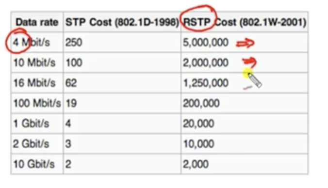
17.1 STP-Optimisation: Etherchannel
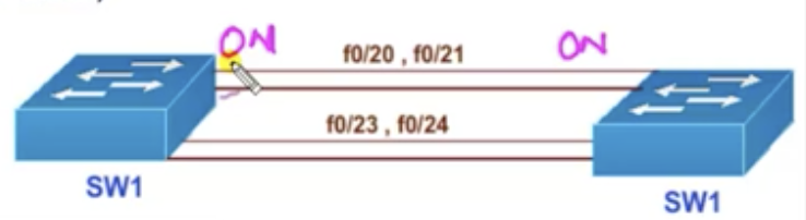
Basics
Ways to enable etherchannel
1. Manual etherchannel by giving an option 'on' to both switches.
2. Dynamic methods using two different protocols. These protocols will negotiate the etherchannel parameters and automatically combine the links based on the parameters. The two different protocols are:
- Used to aggregate bandwidth between multiple L2/L3 interfaces.
- It increases bandwidth and provides redundancy by aggregating individual links between switches.
- Say, you've got 4 links between switches. Three links are going to be disabled temporarily anyways when one of the links is operating. But with EtherChannel, you could combine these 4 separate links into one logical link, increasing the bandwidth quadruple. At the same time there will not be loops.
- Also called link aggregation or port channel interfaces.
- You could use this link as L2/L3. This means you could use L2 interface to forward normal switch traffics and L3 interface to assign an IP address to use it as a L3 port.
- Even if one link fails, the rest of the links would still be working.
- EtherChannel load balances traffic over all the links in the bundle.
- Up to 8 links can be used to combine into one logical link. But you should ensure that all the links must have the same bandwidth, duplex and VLAN setups.
- EtherChannel can be configured as layer 2 or layer 3.
- Port-channel is the logical instance of the physical interfaces.
Ways to enable etherchannel
1. Manual etherchannel by giving an option 'on' to both switches.
2. Dynamic methods using two different protocols. These protocols will negotiate the etherchannel parameters and automatically combine the links based on the parameters. The two different protocols are:
- PAGP (Port aggregation protocol)
- Cisco proprietary (need Cisco on both switches)
- Modes: Auto & Desirable
- LACP (Link aggregation control protocol)
- Open standard
- Modes: Passive & Active
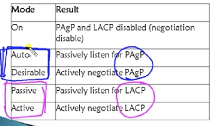
PAGP
LACP
Possible combinations (on SW 1 and SW 2):
- Desirable mode: A switch would actively initiate messages and reply to any initiated messages
- Auto mode: only replies to initiated messages.
LACP
- Passive mode: Auto mode in PAGP
- Active mode: Desirable mode in PAGP
Possible combinations (on SW 1 and SW 2):
- on on
- desirable desirable
- desirable auto
- active active
- active passive
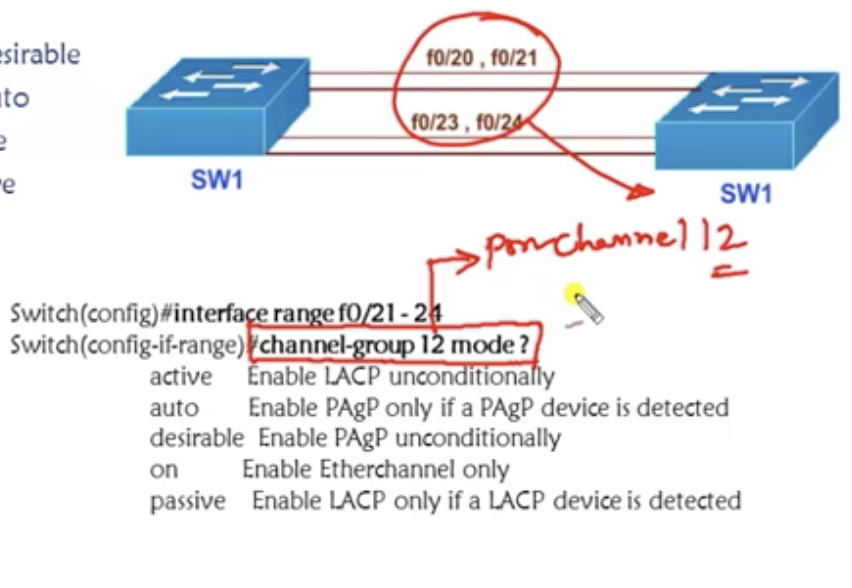
Configuration explained
- 12 means you are going to combine t`he four separate ports (20, 21, 23, 240 into one logical port, port channel being 12.
- Note that you need to run this configuration on both switches.
- for verification, use: show etherchannel summary or show ip interface brief (you can see the logical interface created there).
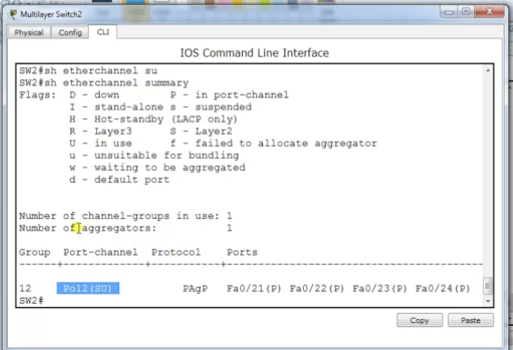
Note on trunking
- if you configure trunking on the port channel that combines several interfaces, all the interfaces in that port channel are going to be applied with trunking.
17.2 STP-Optimisation: BPDU guard and filter
Looking back at PortFast
BPDU Guard: basics
BPDU Guard: Configuration
On a switch,
Check if an interface is in an error-disabled state on a switch:
Recover a error-disabled port:
- It greatly reduces the convergence time by bypassing the listening and the learning states. However it may at the same time raise some security issue.
- For example, you may have a switch accidentally connected to a PortFast port on another switch, which is not desirable (may create a loop).
- So you wanna ensure that you do NOT have such cases. The solution is the BPDU guard.
BPDU Guard: basics
- BPDU Guard prevents loops if another switch is attached to a PortFast port
- When BPDU Guard is enabled on an interface upon receiving a BPDU message from another switch, it is put into an error-disabled state (basically shut down. Cannot do anything)
- It can be enabled at either global config mode (which affects all PortFast Interfaces) or just a single interface mode.
- PortFast does not need to be enabled for it to be configured at a specific interface.
- If PortFast interface on a switch receives a BPDU message, that means there's something wrong-a switch connected to the switch. This is because only switches can generate BPDU msg. End-user devices cannot understand or generate BPDU messages.
BPDU Guard: Configuration
On a switch,
- configure terminal
- spanning-tree portfast bdpuguard default
- OR
- configure terminal
- interface f0/2
- spanning-tree bdpuguard enable
- THEN
- show spanning-tree summary totals
Check if an interface is in an error-disabled state on a switch:
- enable
- show interface status err-disabled
Recover a error-disabled port:
- configure terminal
- interface <interface number>
- shutdown (manual shutdown)
- no shutdown (manual reboot)
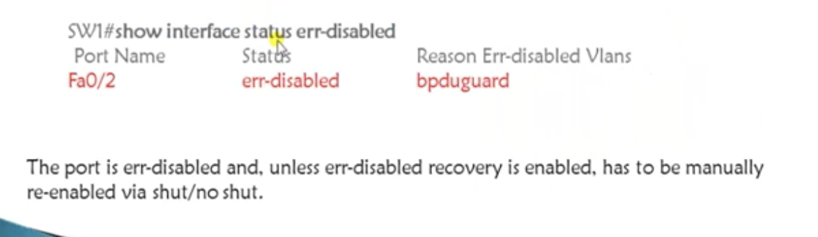
show interface status err-disabled
BPDU filter
Configuration
Global config vs Interface mode
- slightly different from BPDU filter
- instead of putting the port into an error disabled state, it is going to disable PortFast (means to re-enable STP).
Configuration
- configure terminal
- spanning-tree portfast bdpufilter default (global config)
- OR
- interface <interface no> (interface mode)
- spanning-tree bdpufilter enable
Global config vs Interface mode
- In both cases, the port will not go into an error disabled state. It is going to reenable STP.
- In global config mode: if a portfast interface receives any BPDUs, it removes PortFast to enable STP again.
- in interface mode: the interface is going to ignore BPDU. It is NOT going to run STP and at the same time it is going to ignore the received BPDU. It does not go shutdown.
17.3 STP-Optimisation: RSTP lab
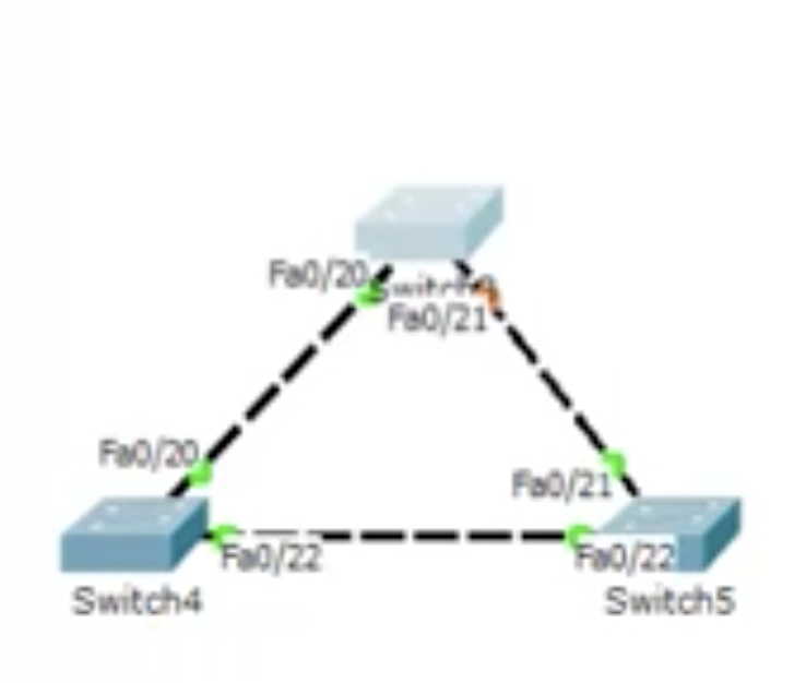
1. STP is by default applied for switches.
2. You want to change that to RSPT. Do on ALL switches:
2. You want to change that to RSPT. Do on ALL switches:
- configure terminal
- spanning-tree mode rapid-pvst
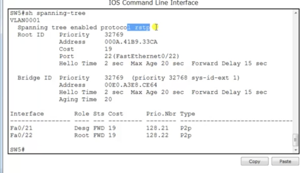
4. If you fail a port to a direct link, the other port will immediately be changed to a forwarding state.
5. If you get that link back on, it is going to go back to original in a sec.
6. if you connect end-user devices to a switch, the listening and learning states will be skipped.
5. If you get that link back on, it is going to go back to original in a sec.
6. if you connect end-user devices to a switch, the listening and learning states will be skipped.
18.1 Access control list: introduction
Basics
- ACL is a set of rules which will allow or deny a specific traffic moving through a router
- It is a layer 3 security which controls the flow of traffic from one router to another
- it is also called Packet Filtering Firewall
